The Lab
As network engineers, we need access to network devices to build and deploy networks. However, we want to do it in a safe way such that we don't interfere with our existing home or business network, open or expose our network or devices to outsiders, or misconfigure our network in a way that prevents us from getting to the rest of our network or the Internet. That is where the Lab comes in.
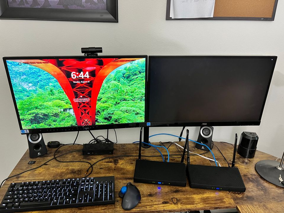
The lab is our current implementation of a semi-isolated networking environment that we can configure, test and deploy to without interfering or comprising our existing network. It is semi-isolated such that in our current implementation we do have a connection to our network and the Internet to allow for upgrades/patches and such, but only such that all changes we make will not affect the outside network. The current network will provide a DHCP address to the routers for outside access purposes, and we will set up an internal network on the routers for testing purposes. We strongly recommend having a test network lab rather than making changes on a production or existing home network, although you can certainly use the knowledge you learn from your lab environment to enhance your existing network.
What's the difference between a test network and the home/business network I already have?
Well, we're going to be making a lot of setup and configuration changes that if performed on your existing home network could potentially erase your home network settings and prevent you from being able to access your home network or the Internet or expose your devices to others outside your home or business network. That would be bad. We're talking about things such wiping the router configuration, changing network IP address and wireless configurations, changing network features and settings and things that if applied to the network you already have would very much destroy what you already have in place. Setting up an isolated network environment such as this allows you the safety of learning and making changes in an environment that will have no effect on any other devices outside of the devices that are on the test network. A dev/learning environment if you will. A special thanks to Mike Miller for reviewing the article and making suggestions to make our articles better.
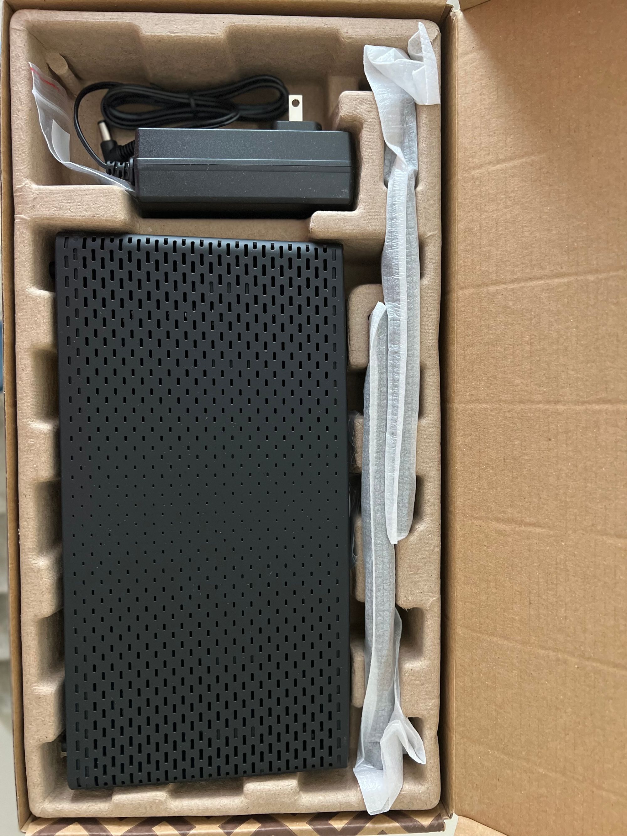
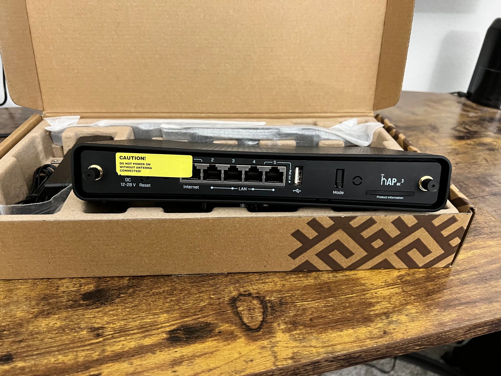
For the current implementation of our lab, we decided to go with two MikroTik hAP ac3 wifi router/switch combo device units. (Note: at the time of this writing, MikroTik has released the hAP ax2 and in future videos we may decide to upgrade to the ax2). The hAP ac3 is a wireless dual-band router with 5 Gigabit Ethernet ports and external high gain antennas. It has 256MB of RAM and a quad-core CPU, POE support, a 128 MB NAND and a full size USB port to add additional storage and it retails for around $109.00 USD. If you are on a more restrictive budget, you can do the lab examples with other MikroTik hardware such as the hEX (minus the WiFi configuration) or the hAP/wAP series devices.
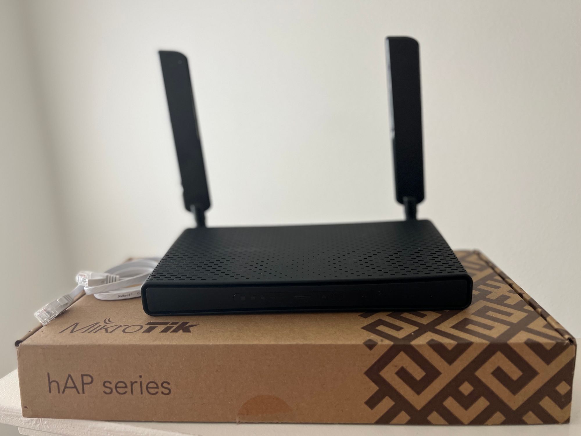
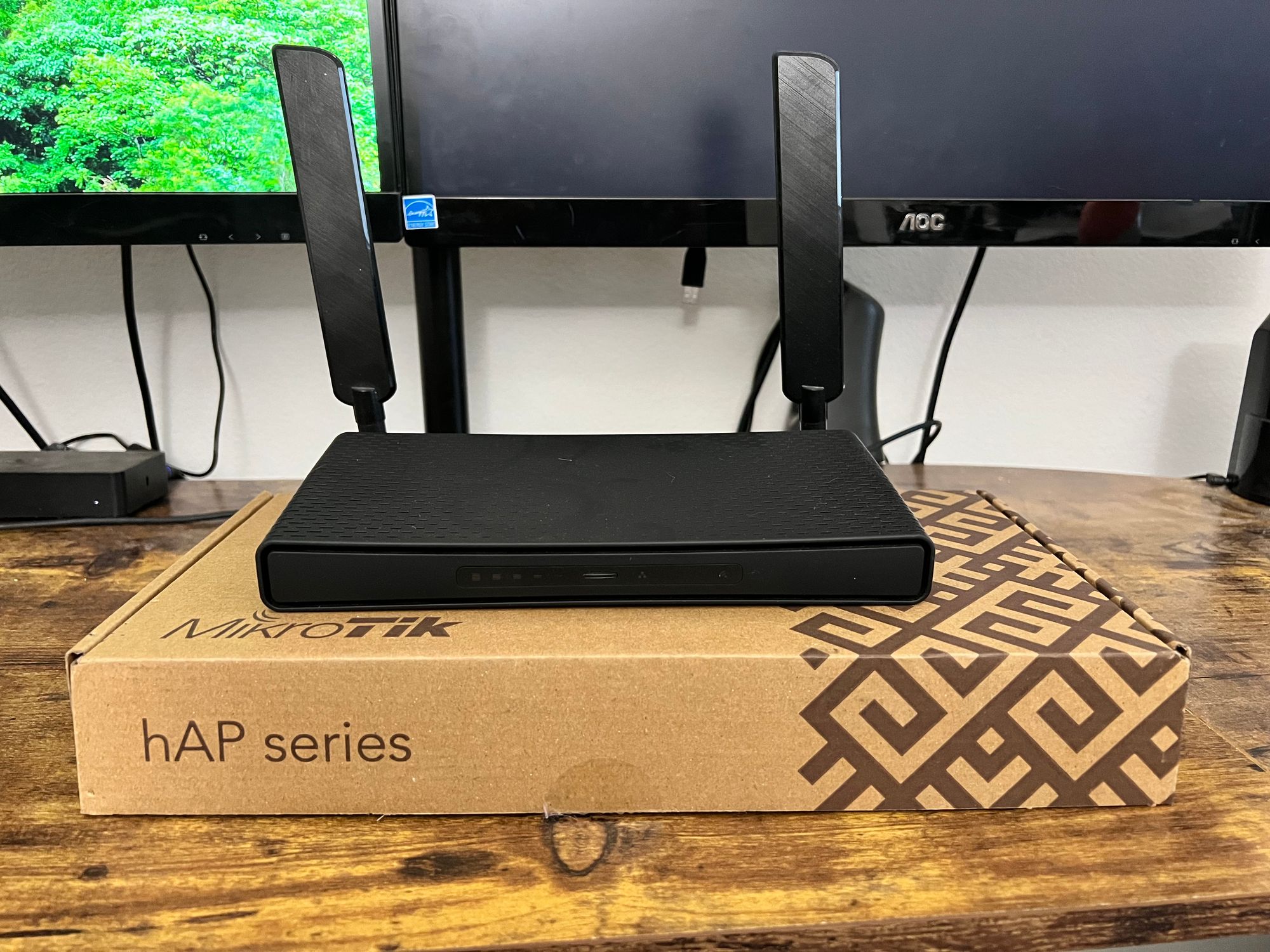
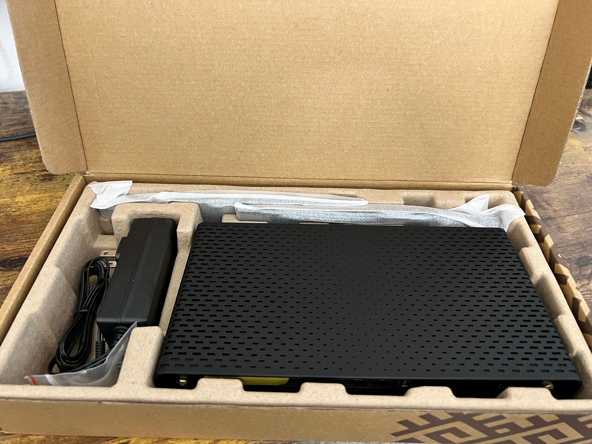
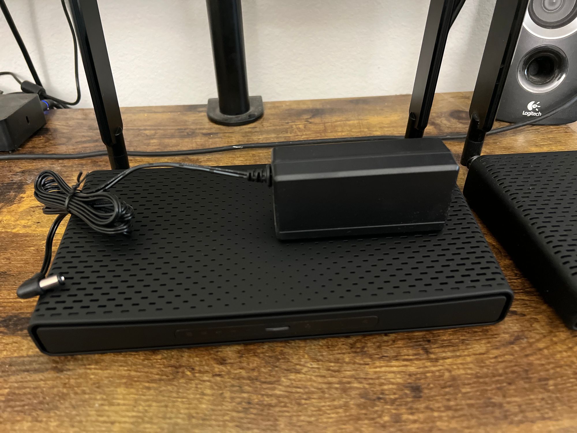
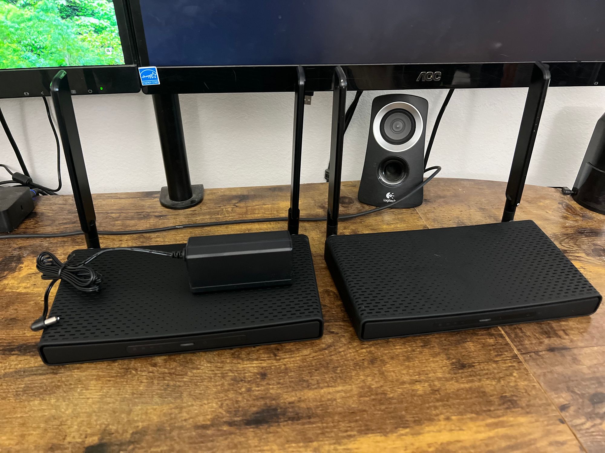
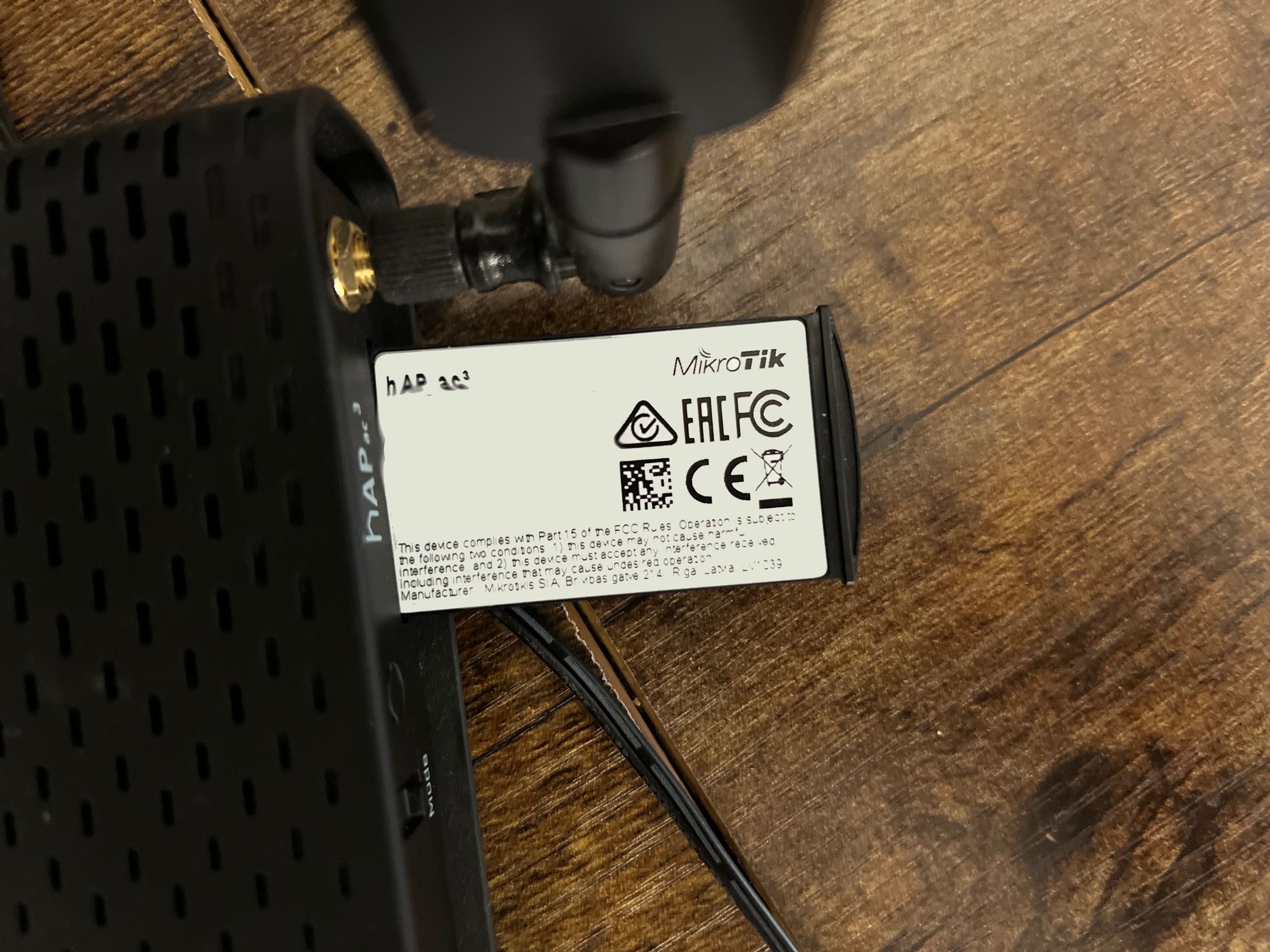
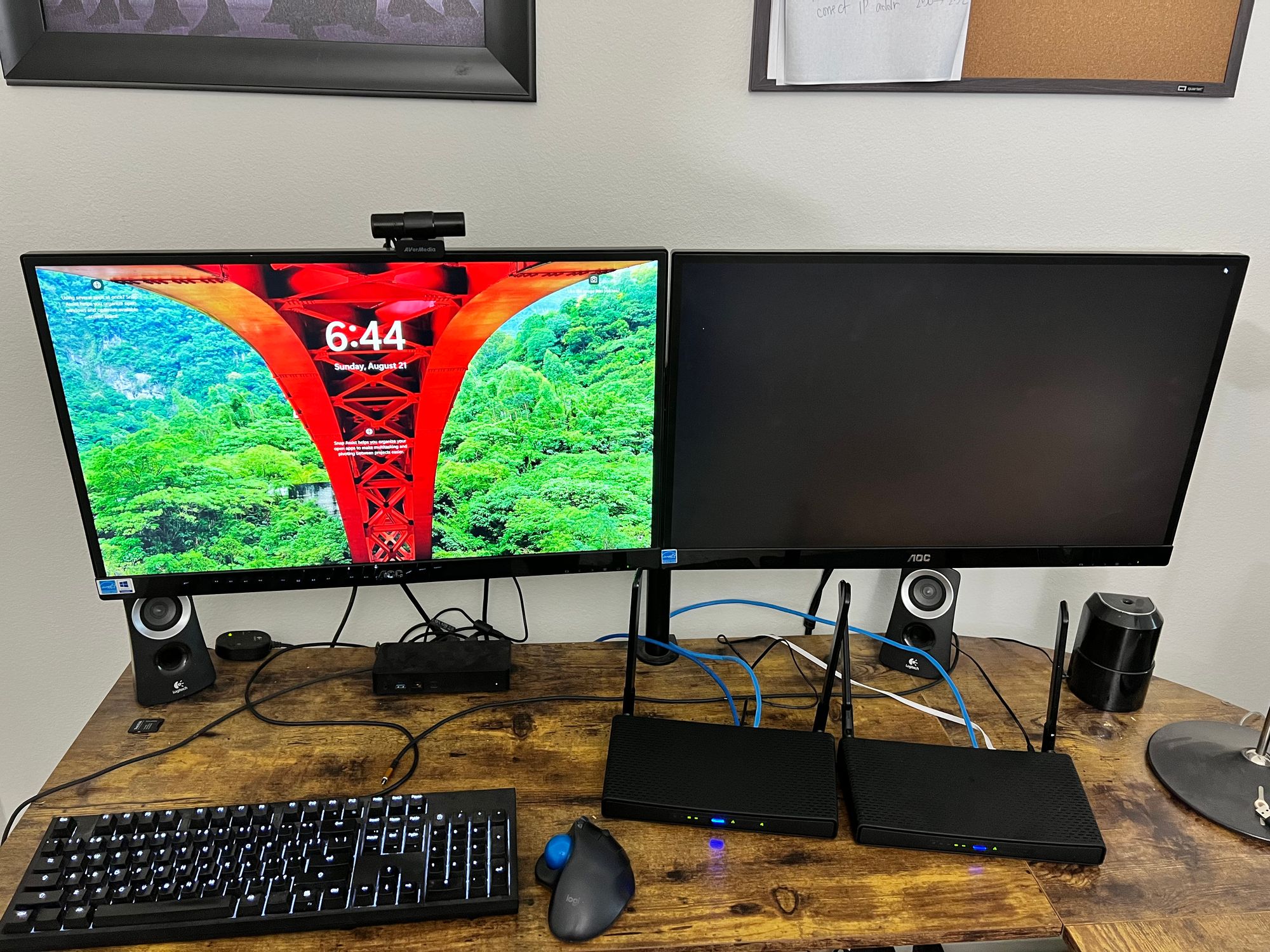
This implementation cost around $220 USD for the two Mikrotik hAP ac3 units and the ethernet cables. The hAP ac3 units are great devices that will allow us to test our deployments, setups and configuration before pushing it out to a live environment.
We recommend using good quality CAT6 network cables for your lab. While CAT5e cables will suffice, given the availability and pricing of CAT6, for all our lab and production runs, we only install CAT6 or higher cable. (CAT5e is rated for networks up-to and including 1Gb, whereas CAT6 cables are rated up to 10Gb networks.
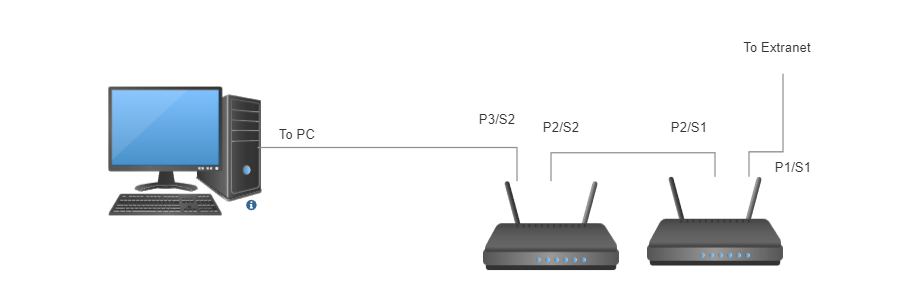
Port Setup:
To setup your lab, you will need three CAT6 network cables. For our network setup, we have two router/switch combinations that we are calling switch 1 (S1) and switch 2 (s2) The first cable we suggest connecting from the back of your existing router/switch to Port 1 of switch 1 (P1/S1). This will give switch 1 the ability to access the Internet. Secondly, connect your second CAT6 ethernet cable from Port 2 of Switch 1 (P2/S1) to Port 2 of Switch 2 (P2/S2). This cable will be used to connect the two switches together to allow them to talk to each other and will be used as a bridge network between switch 1 and switch 2. The third cable will be connected from the spare network card on the back of your PC to the switch (PC to port 3 switch 2 (P3/S2). This will allow you to be able to access and talk to both switches.