MTCRE Lab 1.10 - Routing Marks and Policy Based Routing

Introduction
Traditional routing makes forwarding decisions based solely on the destination IP address. Every packet headed to the same destination follows the same path, regardless of where it came from or what application sent it. This is sufficient for simple networks, but it breaks down in dual-ISP environments, traffic engineering scenarios, and situations where different users or services must use different upstream providers.
Policy-Based Routing (PBR) in MikroTik RouterOS lets you override destination-based routing by tagging packets with a routing mark in the mangle firewall chain, then defining separate routing tables whose routes apply only to tagged packets. The result is precise, per-flow control over which path a packet takes—without touching the main routing table that governs all other traffic.
This lab builds a dual-ISP gateway from scratch. R1 is the customer edge router connected to two ISPs: R2 representing ISP1 and R3 representing ISP2. Two hosts sit on R1's LAN. Without PBR, both hosts exit through ISP1. After completing the exercises, you will have configured routing tables, mangle rules, and connection-mark chains so that each host consistently uses a different provider—verified end-to-end by pinging ISP-specific destinations.
You will also deliberately break the configuration in specific ways to understand the failure modes that make PBR notoriously difficult to troubleshoot: silent fallback to the main table when a routing table lacks the fib flag, marks that never match because the wrong mangle chain was chosen, and routing table name mismatches that go undetected until you check packet counters.
By the end of this lab you will be able to design, implement, verify, and troubleshoot policy-based routing for real-world dual-ISP and traffic-steering scenarios.
Terminology Definitions
Policy-Based Routing (PBR): A routing method where forwarding decisions are based on policy criteria beyond destination IP alone—source address, incoming interface, protocol, destination port, or any attribute the firewall can classify.
Routing Mark: A transient label applied to a packet by the mangle firewall chain. When a packet carries a routing mark, RouterOS performs the routing table lookup in the named table that matches that mark instead of the main table.
Named Routing Table: A routing table other than main. In RouterOS 7.x, named tables must be explicitly created with /routing table add before routes can be assigned to them.
FIB (Forwarding Information Base): The compiled table used for actual packet forwarding. In RouterOS 7, a named routing table must be created with the fib flag to participate in real forwarding decisions. Without it, the table holds routes but cannot forward traffic.
Mangle: The MikroTik firewall subsystem for modifying packet properties—marks, DSCP, TTL, and more. Routing marks must be applied in the prerouting chain, which runs before the routing engine makes its forwarding decision.
Prerouting Chain: The mangle chain that processes packets before routing decisions are made. This is the only chain where routing marks are effective for transit traffic.
Output Chain: The mangle chain for traffic originated by the router itself (pings from CLI, routing protocol packets, management sessions). Routing marks in output affect locally-generated traffic; prerouting handles everything else.
Connection Mark: A mark stored on the connection tracking entry rather than on an individual packet. Once set, it persists for the entire lifetime of that connection and is visible to subsequent packets in both directions. Using a connection mark before a routing mark ensures all packets in a flow—including replies—use the same routing table.
Passthrough: A mangle rule parameter controlling whether a packet continues to the next rule after this rule fires. passthrough=no stops further processing, preventing subsequent rules from overwriting the routing mark.
Silent Fallback: The behaviour where a misconfigured routing mark causes RouterOS to silently use the main routing table instead of the intended named table, producing no error message. This is the most common PBR failure mode.
Lab Topology
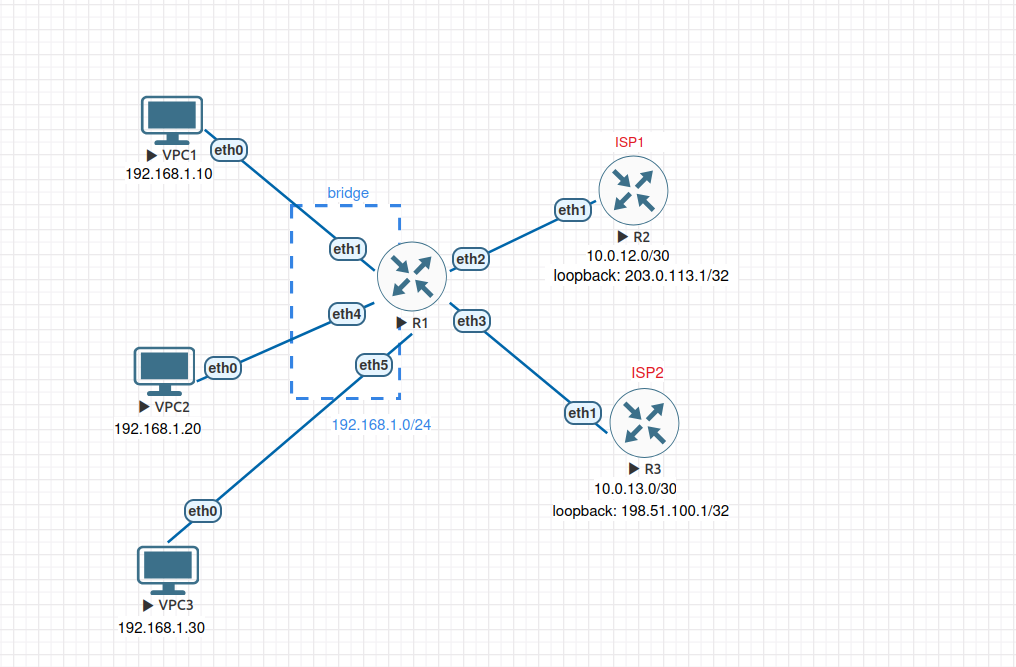
All VPCs share R1's LAN segment. In EVE-NG, connect VPCs to R1's ether1,ether4 and ether5 interfaces, which are members of R1's bridge interface. The LAN IP (192.168.1.1/24) is assigned to bridge, not to the interfaces directly. R2 and R3 each simulate an ISP: they have a WAN link to R1 and a loopback address representing a destination reachable only through that provider.
Network summary:
| Device | Interface | Address | Purpose |
|---|---|---|---|
| VPC1 | eth0 | 192.168.1.10/24 | Host 1 (will use ISP1) |
| VPC2 | eth0 | 192.168.1.20/24 | Host 2 (will use ISP2 via PBR) |
| VPC3 | eth0 | 192.168.1.30/24 | Host 3 (unmatched — used to test protocol-based PBR) |
| R1 | ether1/ether4/ether5 | — | LAN bridge member ports |
| R1 | bridge | 192.168.1.1/24 | LAN gateway |
| R1 | ether2 | 10.0.12.1/30 | WAN1 to ISP1 |
| R1 | ether3 | 10.0.13.1/30 | WAN2 to ISP2 |
| R2 | ether1 | 10.0.12.2/30 | ISP1 router |
| R2 | loopback | 203.0.113.1/32 | ISP1-only destination |
| R3 | ether1 | 10.0.13.2/30 | ISP2 router |
| R3 | loopback | 198.51.100.1/32 | ISP2-only destination |
Prerequisites and Starting Configuration
Complete Starting Configuration
Configure VPC1:
set pcname VPC1
ip 192.168.1.10 255.255.255.0 192.168.1.1
save
Configure VPC2:
set pcname VPC2
ip 192.168.1.20 255.255.255.0 192.168.1.1
save
Configure VPC3:
set pcname VPC3
ip 192.168.1.30 255.255.255.0 192.168.1.1
save
Configure R1:
/system identity set name=R1

/interface bridge add name=bridge comment="LAN bridge"
/interface bridge port add bridge=bridge interface=ether1 comment="LAN port"
/interface bridge port add bridge=bridge interface=ether4 comment="LAN port"
/interface bridge port add bridge=bridge interface=ether5 comment="LAN port"

/ip address
add address=192.168.1.1/24 interface=bridge comment="LAN"
add address=10.0.12.1/30 interface=ether2 comment="WAN1 to ISP1"
add address=10.0.13.1/30 interface=ether3 comment="WAN2 to ISP2"

# Default route via ISP1 only - ISP2 is unused until PBR is configured
/ip route add dst-address=0.0.0.0/0 gateway=10.0.12.2 comment="Default via ISP1"
Configure R2 (ISP1):
/system identity set name=R2-ISP1

/interface bridge add name=loopback comment="ISP1 loopback"
/ip address add address=203.0.113.1/32 interface=loopback comment="ISP1 destination"

/ip address add address=10.0.12.2/30 interface=ether1 comment="to R1"

# Return route so pings from R1's LAN can reply
/ip route add dst-address=192.168.1.0/24 gateway=10.0.12.1 comment="to R1 LAN"
Configure R3 (ISP2):
/system identity set name=R3-ISP2

/interface bridge add name=loopback comment="ISP2 loopback"
/ip address add address=198.51.100.1/32 interface=loopback comment="ISP2 destination"

/ip address add address=10.0.13.2/30 interface=ether1 comment="to R1"

# Return route so pings from R1's LAN can reply
/ip route add dst-address=192.168.1.0/24 gateway=10.0.13.1 comment="to R1 LAN"
Verification:
Confirm both WAN links are up from R1:
/ping 10.0.12.2 count=4
/ping 10.0.13.2 count=4
Confirm the ISP1 destination is reachable but ISP2's is not (main table only has a route to ISP1):
/ping 203.0.113.1 count=4
/ping 198.51.100.1 count=4
The first should succeed; the second should fail with "network unreachable". This baseline confirms the main table has no path to ISP2's address—only PBR will make it reachable for marked traffic.