Lab 3.1 Firewall Workshop

Setup for Lab 3.1 Firewall Workshop

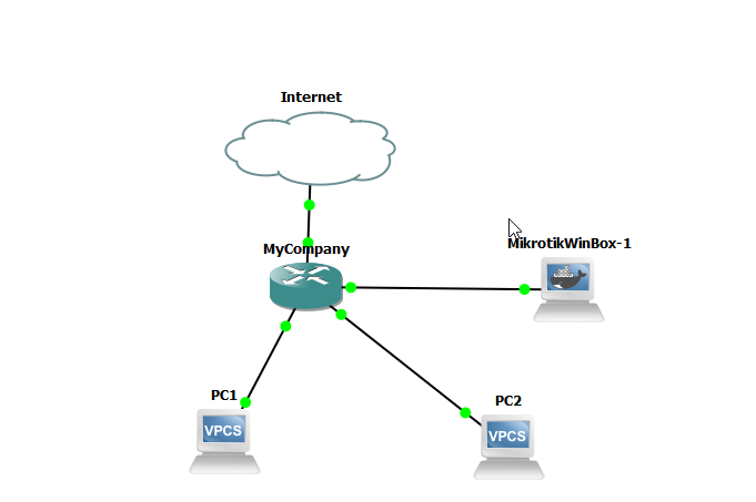
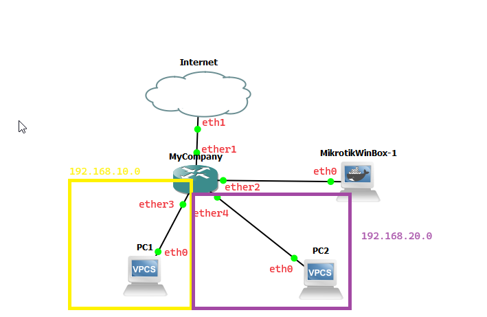
For this lab, we are going to create the following GNS topology. In this scenario, PC1 belongs to department 1 and PC2 belongs to department 2 and we want to set up a firewall to prevent PC1 from being able to connect to the network that PC2 is on and vice-versa. For this scenario, we have added the MikroTik CHR cloud router, 2 VPCS machines, and the MikroTik WinBox appliance to our workspace.

Internet (Cloud1) connected to MyCompany on port ether1
PC1 connected to MyCompany on port ether3
PC2 connected to MyCompany on port ether5
MikrotikWinbox-1 connected to MyCompany on port ether2
MyCompany has two bridged networks set up
bridge1: 192.168.10.1/24 network 192.168.10.0 on ports ether3,ether4
bridge2: 192.168.20.1/24 network 192.168.20.0 on ports ether5,ether6
MyCompany has two DHCP servers set up
dhcp1: 192.168.10.1 / 192.168.10.2-192.168.10.253 on bridge1
dhcp2: 192.168.20.1 / 192.168.20.2-192.168.20.253 on bridge2

Step 1: Add all the appliances to the workspace and create the links between the devices as shown above. If you need a refresher on how to add appliances to the workspace or create links for the devices, please view the following documentation here.

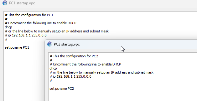
Step 2: Edit the configuration for PC1 and PC2 and set them both to DHCP. (Right click the appliance and Edit Config). Uncomment the dhcp line to enable DHCP.

Enabling DHCP on the VPCS devices

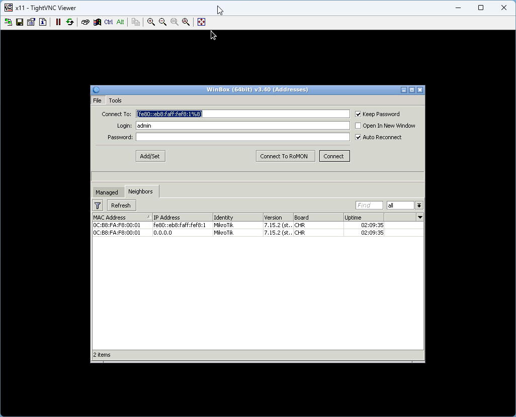
Step 3: Start the CHR and MikrotikWinbox appliances. After the appliances have been started, right click the MikrotikWinBox appliance and select Console to launch the UI. When the appliance has been loaded, log into the device (you may have to use the IP6 address to log into the interface as I've noticed an issue sometimes using the MAC address with the CHR to log in. You can get the IP address from the Neighbors tab)

Step 4: Create the bridge interfaces. Select the Bridge tab from the Winbox menu, and then click the + button to create a new bridge. Name the bridge bridge1. Repeat this step to create another bridge (bridge2). Your bridge setup should resemble the following.

Creating the bridge interfaces

Step 5: With the Bridge window open, select the Ports tab and click the + button to create a port assignment. Assign ether3 interface to bridge1 bridge and click OK. Repeat this step for ether4. Assign ether5 interface to bridge2 bridge and repeat this step for ether6.

Assigning ether3 interface to bridge1 

Step 6: Assign IP addresses to both bridges. 192.168.10.1/24 will be assigned to bridge1, and 192.168.20.1/24 will be assigned to bridge2. Select the IP -> Addresses tab from the MikroTik menu. Click the + button and enter 192.168.10.1/24 for Address, 192.168.10.0 for Network, and bridge1 for Interface and click OK. Click the + button again and enter 192.168.20.1/24 for Address, 192.168.20.0 for Network, and bridge2 for Interface and click OK.

Step 7: Next, create a DHCP server for each network. Select the IP -> DHCP Server tab from the main menu. On the DHCP tab, click the DHCP Setup button to launch the DHCP Server wizard. When the wizard appears, use the following settings to create the DHCP server.

DHCP Server 1:
DHCP Server Interface: bridge1
DHCP Address Space: 192.168.10.0/24
Gateway for DHCP Network: 192.168.10.1
Addresses to Give Out: 192.168.10.20-192.168.10.253
DNS Servers: 8.8.8.8
       8.8.4.4
Lease Time: 00:30:00

DHCP Server 2:
DHCP Server Interface: bridge2
DHCP Address Space: 192.168.20.0/24
Gateway for DHCP Network: 192.168.20.1
Addresses to Give Out: 192.168.20.20-192.168.20.253
DNS Servers: 8.8.8.8
       8.8.4.4
Lease Time: 00:30:00

Setting up DHCP Servers

Note: I usually recommend starting the DHCP server address at .20 this way you can use addresses .2 to .19 for static devices, such as printers, servers, or items that should generally never change IP addresses.  

Step 8: Start both VPCS devices. Once the devices have been started, right click each device and open the console window for these devices. Both devices should have been assigned an IP address on their respective network. PC1 should have a 192.168.10.x address on the 192.168.10.1 network and PC2 should have a 192.168.20.x address on the 192.168.20.1 network.

Step 9: Try pinging PC1 from PC2 and vice-versa. Are you able to ping the other device?

Try pinging the other device

The answer is yes, both devices are pingable from the other device. In a real life scenario, this may represent two subnetworks of a larger network, for example two disparate departments at a company. Our goal is to prevent the two devices from being able to communicate with each other, while also being able to communicate with the Internet. First, we are going to apply our default set of firewall rules to the router, and then we are going to add a set of rules that allows us to prevent communication between the two networks.

Set up Masquerade Rule using Winbox GUI

Step 10: Set up NAT (network address translation) on the router so that our  VPCS devices can access the Internet. To enable NAT, we are going to set up a rule in our firewall. Select IP -> Firewall tab from the main menu and when the Firewall window appears, select the NAT tab. Click the + button to create a new rule.  Set the chain to srcnat and the Out. Interface to ether1 on the General page.

Adding the masquerade rule using the Winbox GUI.

Step 11: Click the Action tab, and set the action to masquerade and click OK to apply the rule.  Test this by attempting to ping a website, such as www.google.com

Before and after applying the masquerade rule

Set up Masquerade rule using Winbox CLI

Alternatively, you can also set up the masquerade rule using the Winbox CLI. Open a New Terminal window from the main menu and when the terminal appears, enter the following command in the terminal.

/ip firewall nat add chain=srcnat action=masquerade out-interface=ether1
Adding a masquerade rule using the WinBox CLI

Import Default Firewall Rules

We are going to use the Python HTTP server to serve local files from our PC to the MikroTik router. Python’s HTTP server can come in handy when you want to quickly share a bunch of files with another device connected to the same network as you. What we are going to do is create a folder and drop the file(s) that we want to share with our MikroTik router in this directory, and then start the HTTP server to serve this directory over HTTP.

If you were following along with the lab earlier you may have already created this directory and downloaded the file to this folder. If so, simply skip ahead to step 13

Step 12: Create a directory on your local PC.  We are going to call our directory SRV.

Inside of this folder, we are going to create a folder called Scripts and place our firewall script inside this folder.

Step 14: Open a Terminal window on your local PC and navigate to the base directory you created earlier (mine is E:\SRV). We are then going to launch Python to serve this directory. Run the following commands to launch the server.

cd E:\SRV *(replace this with your directory if different)*
python -m http.server 

Step 15: We are going to create two interface lists (labels) One for WAN, and one for LAN. Select IP -> Interface List from the MikroTik main menu and select the Interface List tab from the Interface List window that appears. Click the Lists button in the window. When the Interface List window appears, click the + button

Step 16: In the name input box, type LAN and hit the OK button to add the LAN interface list item. Click the + button again and repeat the step to add the WAN interface list item.

Step 17: Next, apply WAN interface to ether1 and the LAN interface to bridge1 and bridge2. With the Interface List Window open on the Interface List tab, click the + button and in thew New Interface List Member Window, set the List dropdown to WAN and Interface to ether1 as shown and click OK.

Setting up the WAN interface

Repeat the following, setting the List dropdown to LAN, and Interface to bridge1. Repeat once more, setting the List dropdown to LAN, and Interface to bridge2.

Both WAN and LAN interfaces defined.

Step 18: Now, download the script from the web server and run the script to apply the firewall settings.

To download, open a new terminal by selecting "New Terminal" from the Winbox main menu. Once terminal is open, run the following command. (Please note, your IP address may be different than the one that is shown here. In that case, you can open the Windows terminal app on your local machine and run the ipconfig command to see what your IP address actually is).

/tool fetch url="http://192.168.150.1:8000/scripts/default_firewall.rsc" mode="http"
Download firewall script.

If we look at the file directory (select "Files" from the Winbox main menu), in the File List we should see our firewall script has been downloaded to the router.

Viewing our file directory. 

Step 19: Open the Firewall filter rules window. (select "IP -> Firewall" from the Winbox main menu and open the Filter rules tab.) As you can see, we currently do not have any firewall rules currently defined, which means that our server is essentially wide-open and unprotected. Let's fix that. We're going to use the console again to run the script that we just downloaded, and then I'll explain what we've just applied. (The script that we are running is part of the default MikroTik configuration script.)

Viewing our empty firewall.

Step 20: Go back to the WinBox terminal, and in the terminal window, we are going to run the script that was just downloaded. To run the script, run the following command in the window.

/import default_firewall.rsc 
Running the script we just downloaded.

If you now take a look at our Firewall window, you will notice that we have added several new rules.

These rules should provide a basic configuration for protecting our router from Internet accessibilty. Now, if we attempt to connect to our router from WinBox on our host PC rather than the one inside our virtual instance, we no longer should be able to.

Rules are processed in the order they are listed. The router checks each packet against the rules sequentially until a match is found. If a packet matches a rule with an accept action, it’s allowed; if it matches a rule with a drop action, it’s blocked; if it matches a reject rule, an ICMP message is sent to inform the sender.

Apply Firewall rules limiting PC1 and PC2 access to each other.

Lastly, create a pair of rules preventing devices on the 192.168.10.x network from being able to access 192.168.20.x network and vice-versa. We are going to create the first rule using the Winbox GUI to demonstrate how it's done in the GUI, and then create the second rule using the CLI to demonstrate how it's done there.

Step 21: Select IP -> Firewall from the Winbox menu. Click the + button to create a new rule.  On this new rule, on the General tab we are going to set:
Chain: forward
Src Address: 192.168.10.0/24
Dst Address: 192.168.20.0/24

Creating the Firewall Rule (GUI) - General Tab
Setting action on firewall rule.

and on the Action tab we set the Action to drop. For this exercise, we are also going to enable logging so that we can see what is happening on our router. Click the Log checkbox and set the Log Prefix to dropped_packets.  

Step 22: Click the Comment button to create a descriptive comment for the new rule we are creating and then click OK to close the window and OK again to apply the firewall rule.

Setting comment on new Firewall rule.

Creating complimentary firewall rule using Mikrotik CLI

The first rule we created prevents devices on the 10.x network to communicate with computers on the 20.x network. This in theory should prevent communication between the two networks, but we recommend creating the complimentary rule prevening devices on the 20.x network communication with devices on the 10.x network as well. To create the complimentary rule using the CLI open the Terminal window, and type the following into the Terminal

/ip firewall filter add action=drop chain=forward comment="prevent 20.x network from being able to access 10.x network" dst-address=192.168.10.0/24 log=yes log-prefix=dropped_packets src-address=192.168.20.0/24

Step 22: Go back to PC1 and attempt to ping the IP address of PC2. Then, go to PC1 and attempt to ping the IP address of PC1. We are no longer able to ping or communicate across devices because we have created firewall rules to block devices on one network from being able to access devices on the other network. Now, if you take a look at your logs,  by clicking the Log item in the Winbox menu, you should see that access to and from both networks has essentially been blocked. Click on one on the dropped_packets rules to show what happened.

Log setting showing blocked packets. 

This is in essence one of the key features of the firewall – to control which traffic is allowed to enter or leave a network based on predefined security rules. They can allow or block traffic based on IP addresses, port numbers, protocols, or other criteria.