Lab 2.2 - First Interactions with the MikroTik Router (WinBox)

Step 1: Create a new GNS3 workspace
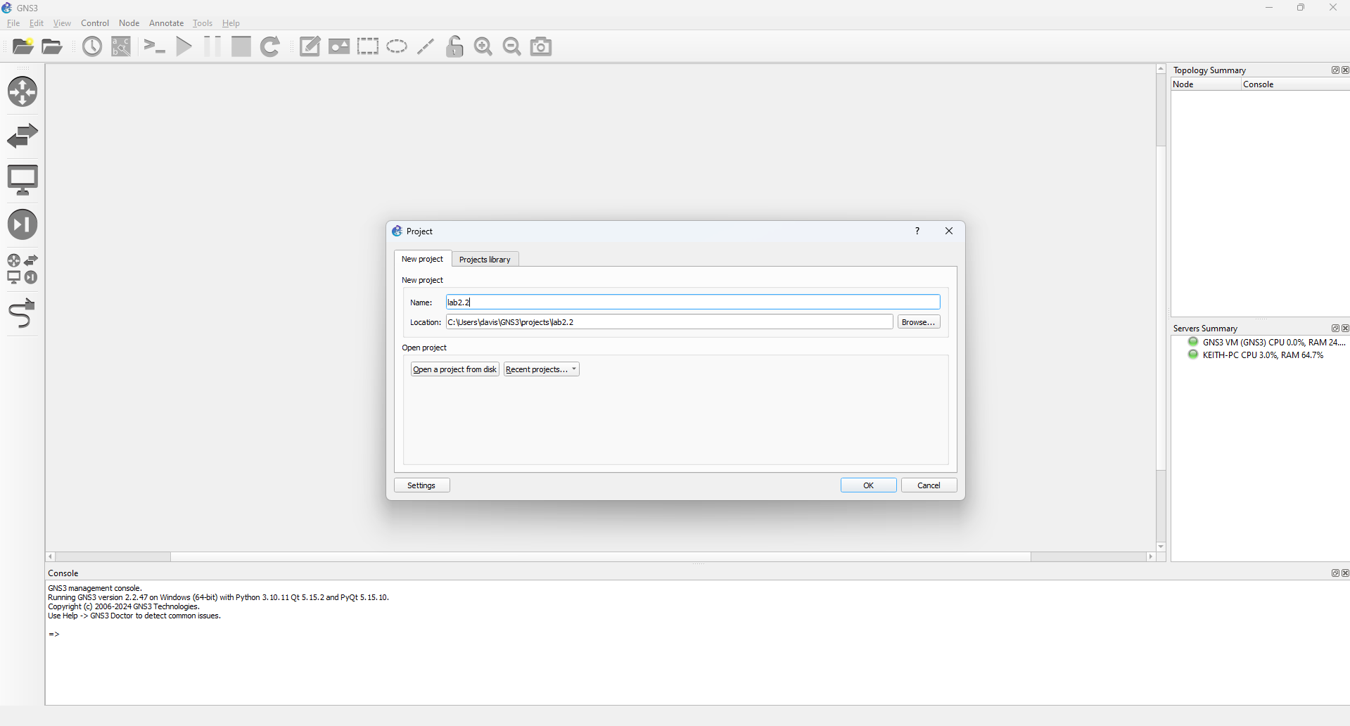
- Open GNS3. When the project screen appears, enter the new project details as follows. If the screen doesn't open, go to File -> New Blank Project (or hit CTRL+N on your keyboard). Hit OK to continue.
To this workspace, we are going to add a Cloud node, a MikroTik CHR node, and a VPCS node. The Cloud node will enable us to access the workspace nodes from our local machine, the MikroTik CHR node will provision a router for us, and the VPCS node will provision a client that we can use to test our setup.
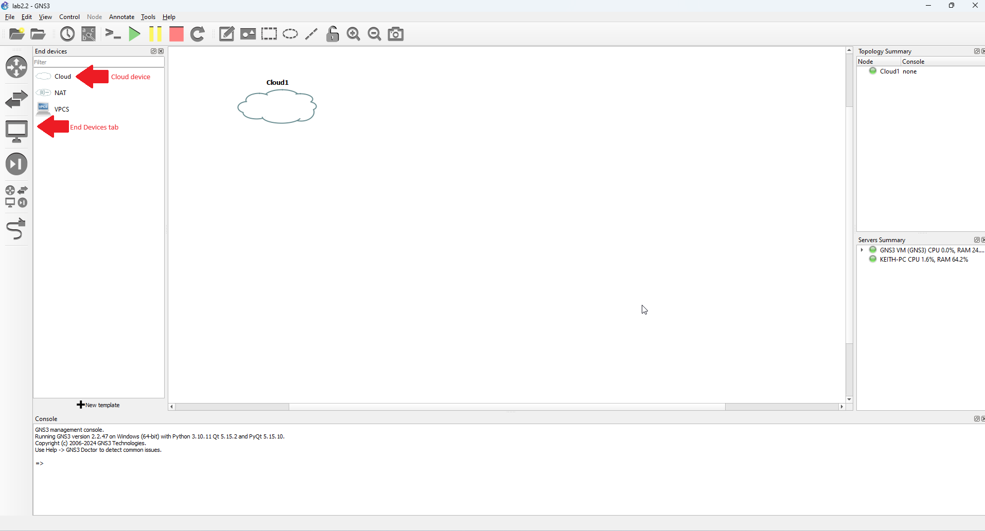
2. Let's add the Cloud node. Under the End Devices tab, select the Cloud node and drag it onto the blank workspace area. You should end up with something similar. When asked to choose a server, select GNS3 VM from the list and hit the OK button.
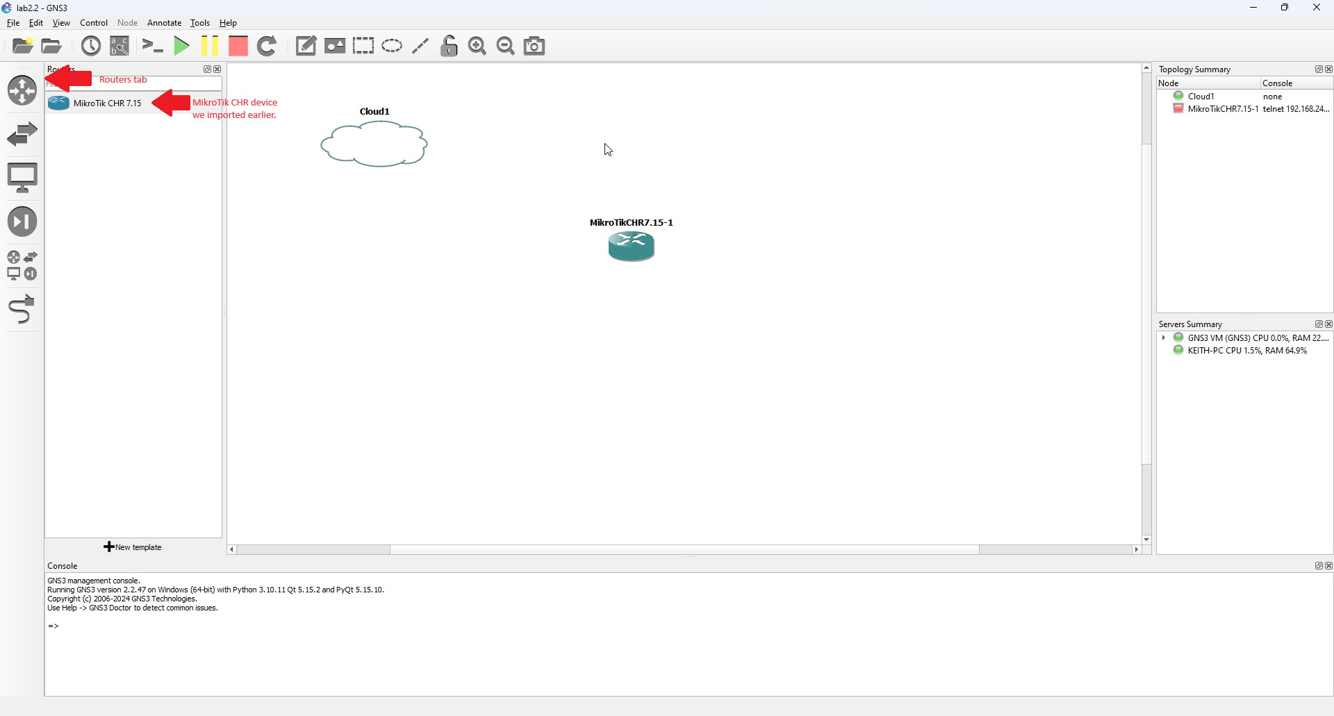
3. Next, add a MikroTik CHR node to the workspace. Under the Routers tab, select the MikroTik CHR router device we imported earlier and drag it onto the blank workspace area. Again, choose GNS3 VM as our server when prompted.
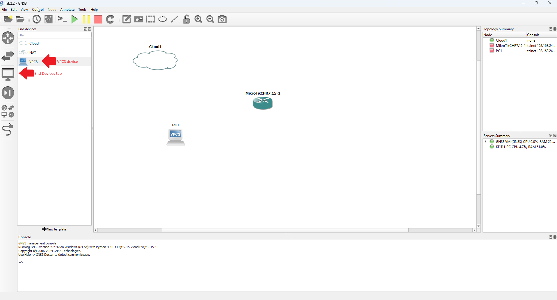
4. Next, add a VPCS node to the workspace. This is a console device that will let us test connectivity for the device. Again, Under the End Devices tab, this time, select the VPCS node and drag it onto the blank workspace area. You should end up with something similar. When asked to choose a server, select GNS3 VM from the list and hit the OK button. Your workspace should resemble the following.
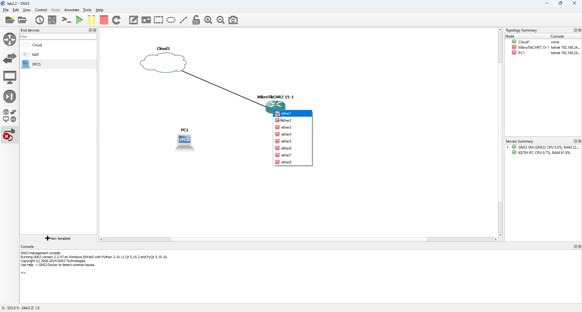
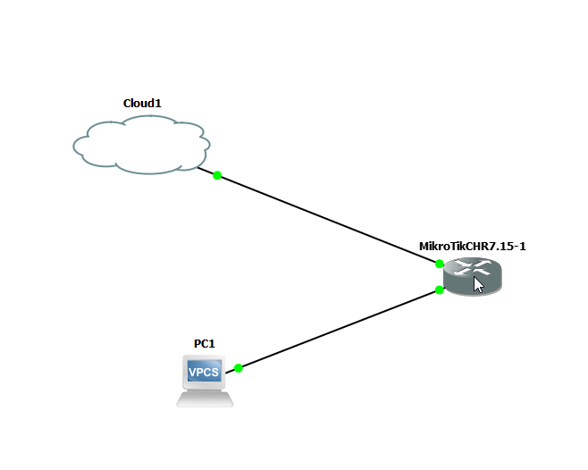
5. Next we need to create the connections between the devices. This simulates the physical ethernet connections that we would use to connect the devices to the Internet. We are going to connect the cloud eth-1 device to the CHR's ether1 and we will connect port 2 on the router (ether2) to the VPCS node (eth-0)
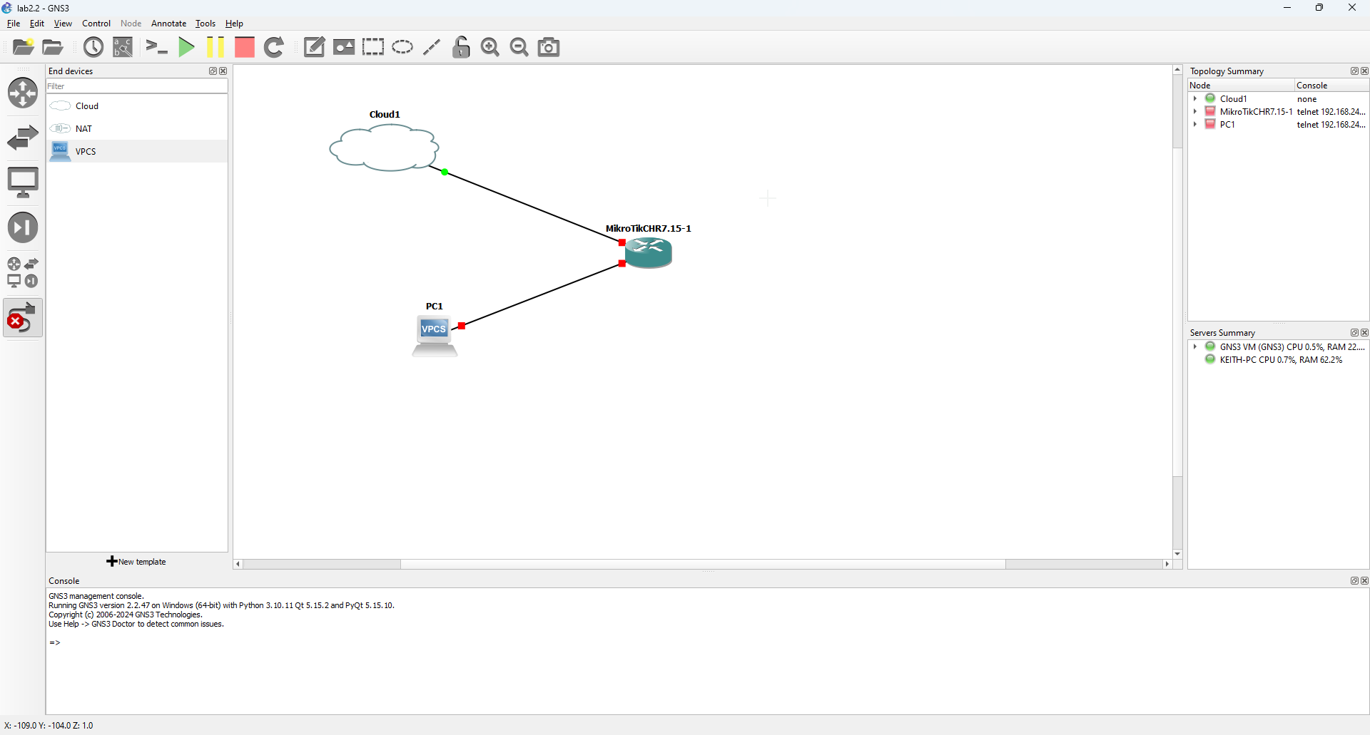
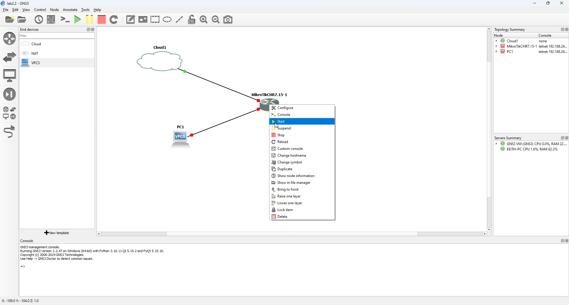
6. Notice the green dot next to the Cloud1 interface and the red dots next to the CHR device and the VPCS device. This is indicative of the node status. Red dots indicate that the interface is inactive, and in this instance, it is because the devices are currently not running. Green dots indicate that the interface is active. Next we are going to start the CHR router and the VPCS device. We are going to start the router first, and then we have one additional configuration we need to make to the VPCS device before we start it. Right click on the MikroTik CHR node in our workspace and select Start from the pop-up menu that appears.
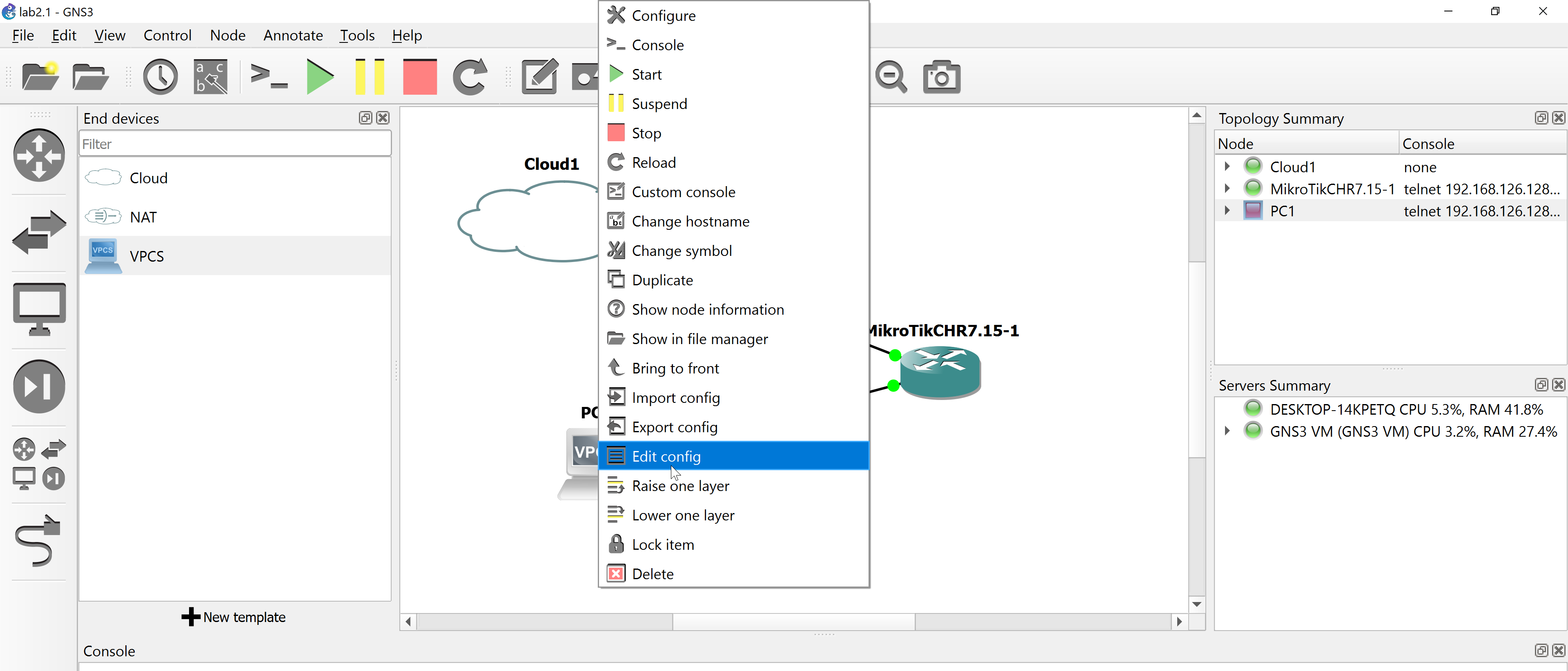
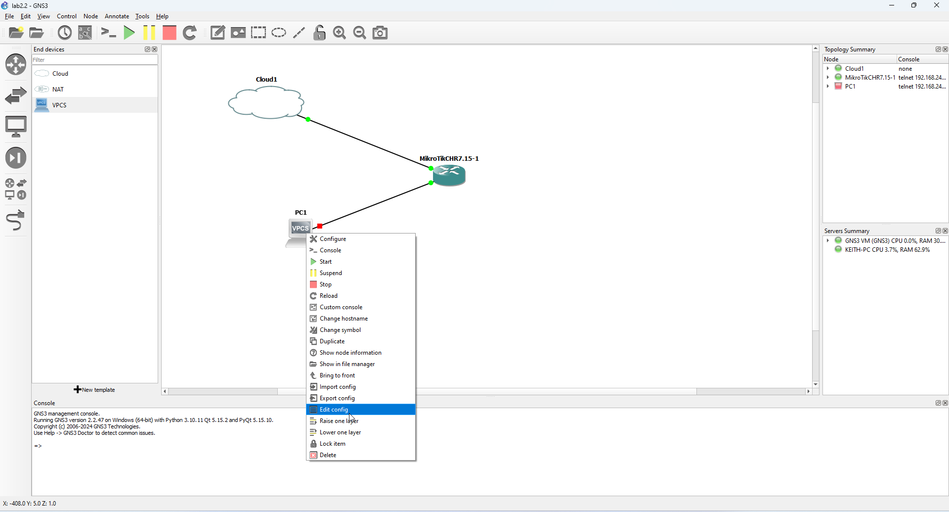
7. We are going to start the VPCS device next, but before we do, we want to enable DHCP on the VPCS node, so that the virtual PC will be able to grab an IP address from the router. To make this change, right click the VPCS node and select Edit Config from the pop-up menu that appears.
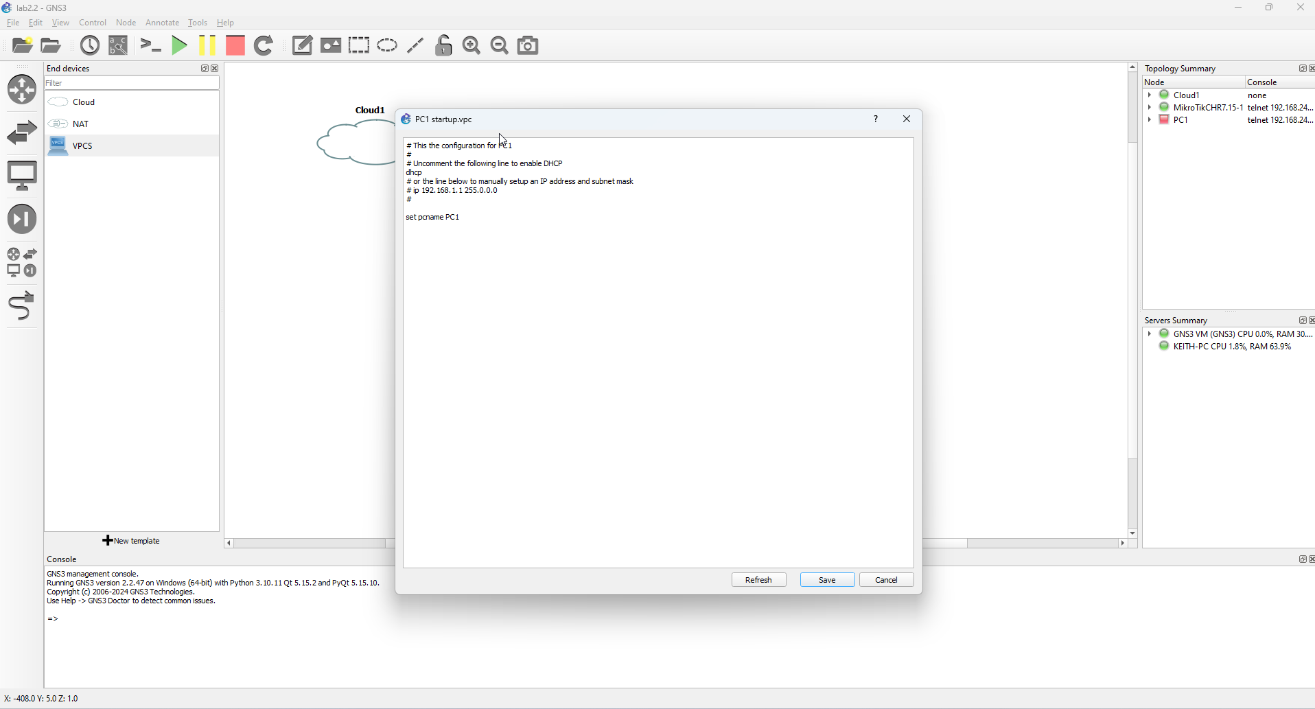
8. Uncomment the dhcp line from the config as follows and then save the config by hitting the Save button at the bottom of the screen.
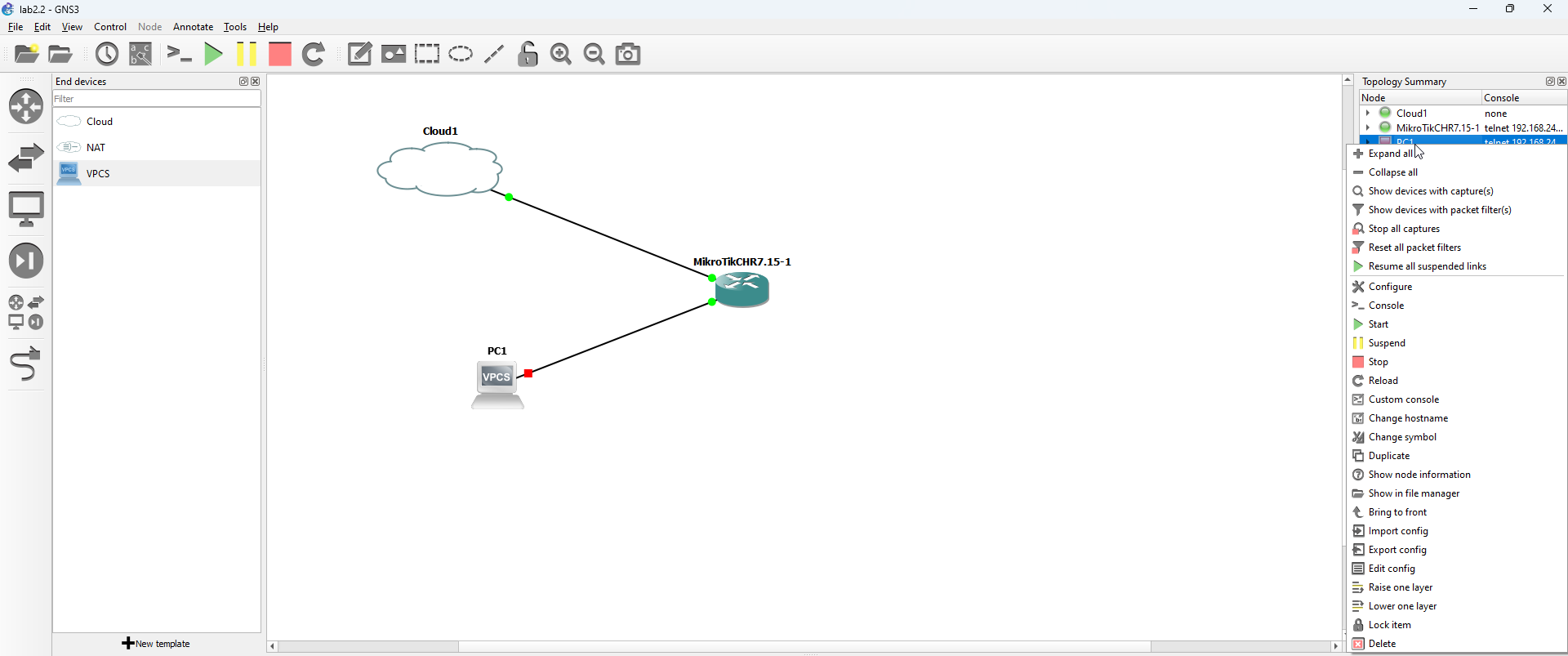
We are now going to start the VPCS device. We can also start nodes by right-clicking them in the Topology Summary window and select Start from the menu that appears.
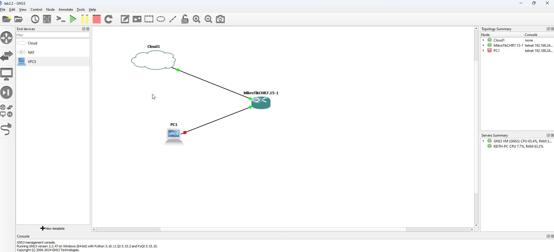
Your network topology should resemble the following screen. We are going to use this basic setup for the first few exercises.
Step 2: Log In to the Router (Console)
We are going to log in to the router using the GNS3 console. This will allow us to see pertinent information about the router, such as the IP address we will use to access the router.
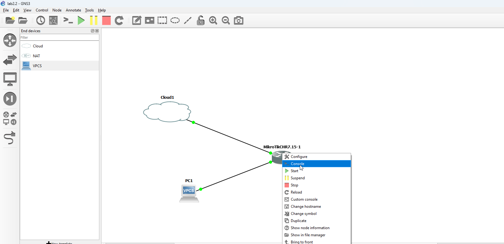
- Right click on the CHR node and select Console from the pop-up menu that appears
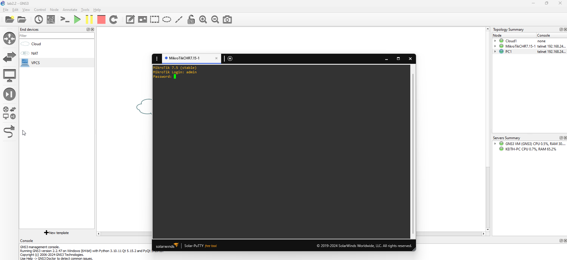
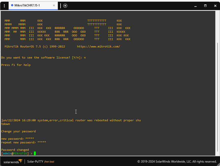
2. When the console appears, log in to the console using the default username (admin) and password (hit the ENTER button - there is no password assigned by default).
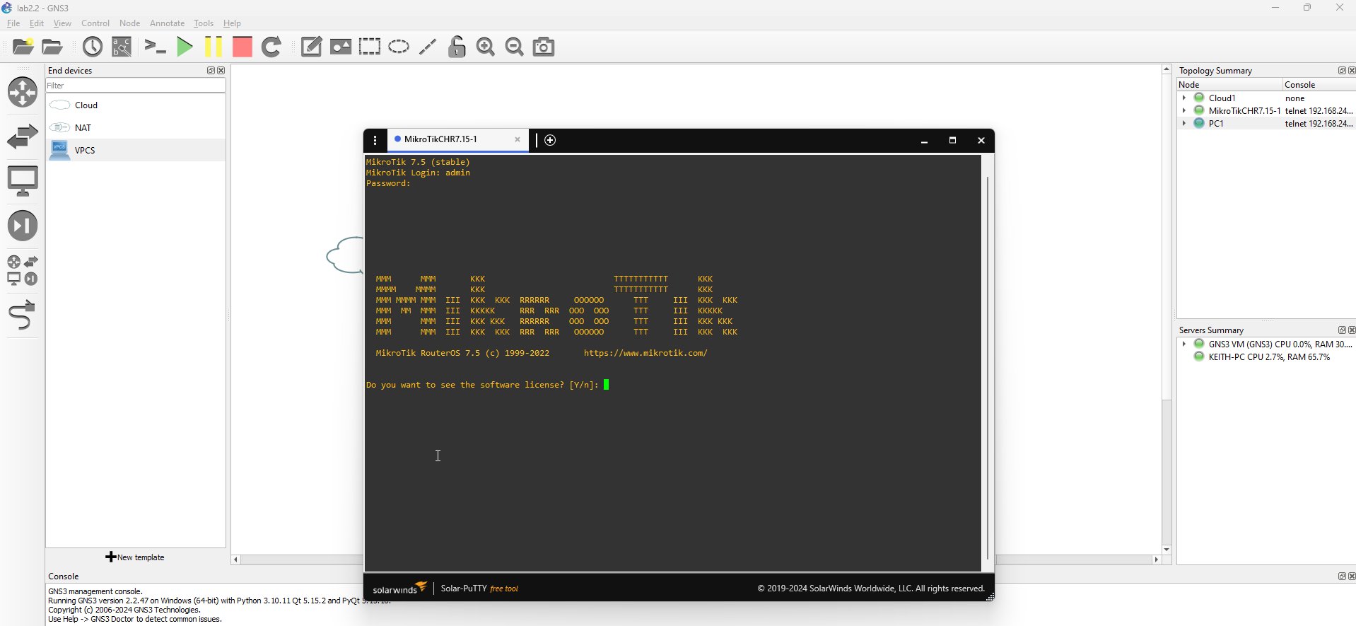
3. When you have logged in for the first time, you will be asked to accept the license agreement. If you've never viewed the CHR license, you can type Y to view the license agreement or N to skip. We are going to skip viewing the license agreement (you should read this at some point)
4. You will be prompted to set a password for your console. In real-world usage, we would want to set a complex hard-to-guess password, but for practice with our console, we can use a much simpler password. Set a password for the device and hit ENTER, and when prompted, re-enter the password and ENTER again.
We need to get the IP address of the MikroTik interface so that we can log into the router. An easy way to get the IP address of the public interface (in this case our public interface is ether1), type the following two commands in the console to get the IP address.
:global addr [/ip address get [find interface="ether1"] address]
:put $addr
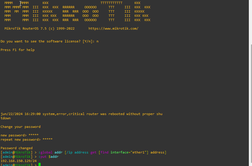
From the image, you can see our IP address is 192.168.150.129. The /24 denotes the subnet (255.255.255.0)
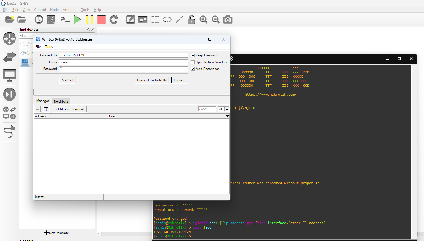
Knowing our IP address, we are going to log into our router using MikroTik Winbox. Open your the app, and enter the IP address of the router in the Connect To input box, enter admin in the Login input box, and enter the password that you set earlier in the password box and hit the Connect button to log in.
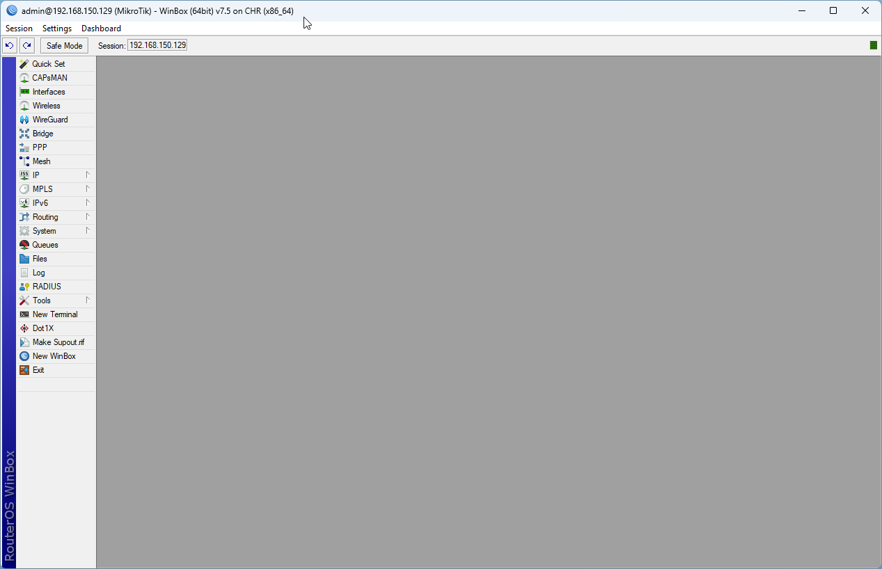
Step 3: Change the router password
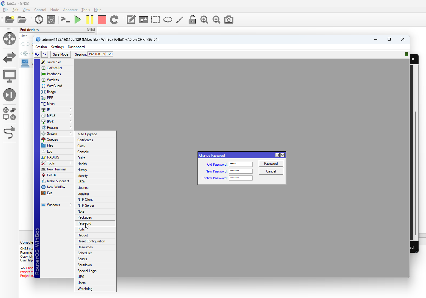
- We are going to change the password of the router using the app. To do so, select System -> Password from the menu bar. On the Change password pop-up screen that appears, enter the current password in the Old Password input box, and enter the new password in the New Password input box and retype the new password in the Confirm Password box and hit the Password button to assign the new password to the router.
Step 4: Change the Router Hostname
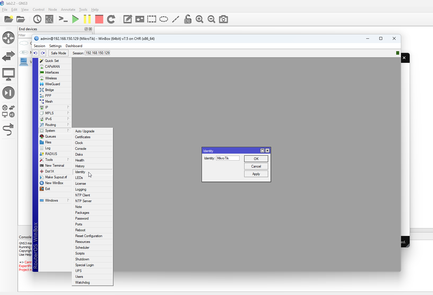
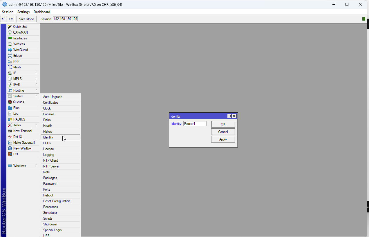
- The default hostname for the MikroTik router is MikroTik. We are going to change the hostname for the router to Router1. To do so select System -> Identity change the name from MikroTik to Router1 as shown below and click the OK button.
Step 5: Create a local network and test
Our next step is to create a local area network, connect our VPCS device to the local network, and then test our VPCS to see if it has an IP address and if it is able to access the Internet.
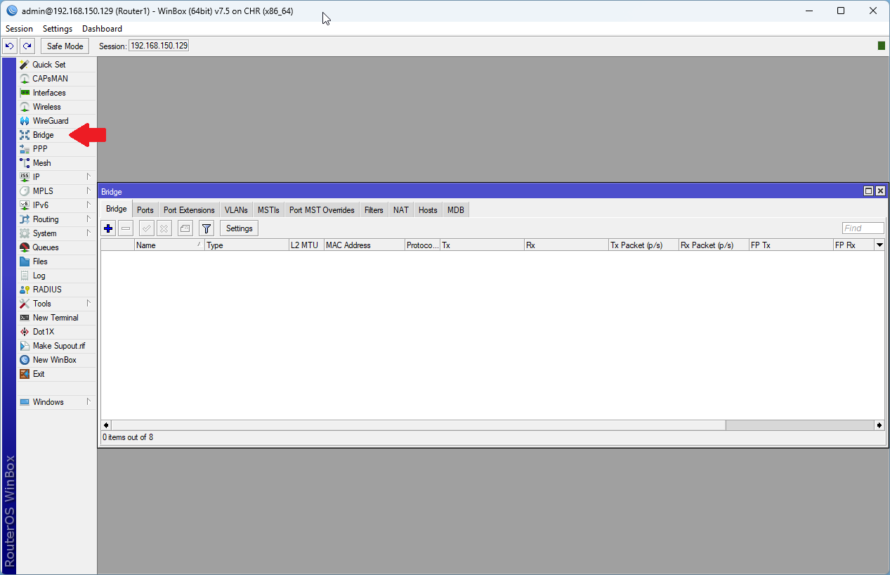
- The first thing we are going to do is to bridge the remaining network ports to create a virtual bridged interface. What this does is allow devices connected to different physical interfaces to communicate as if they were on the same network segment. In other words, regardless of which port we connect to on our router, the devices will communicate as if they are on the same network. To do so, select the Bridge tab from the menu bar.
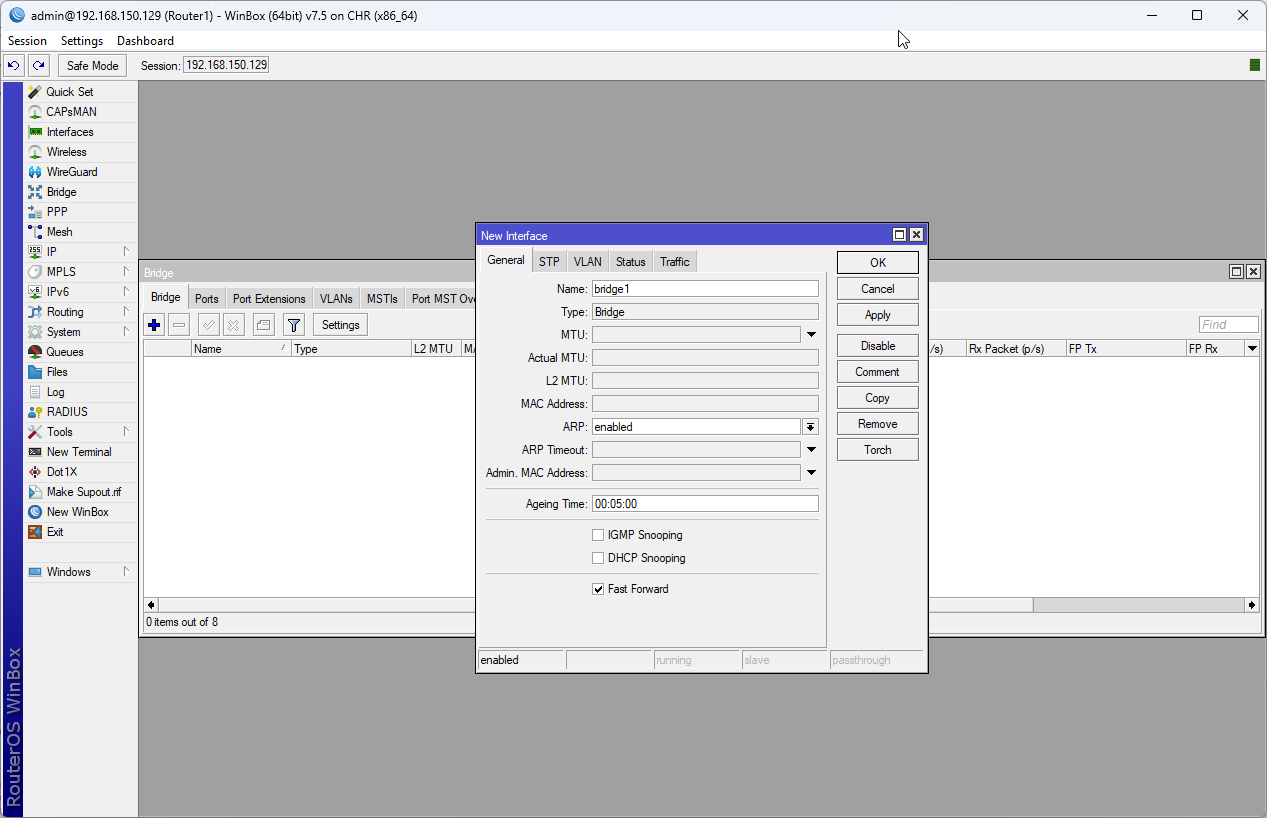
2. Click the + button on the bridge tab. It will bring up the New Interface window. We are going to leave the name for our bridge as bridge1. Click OK to create the new interface.
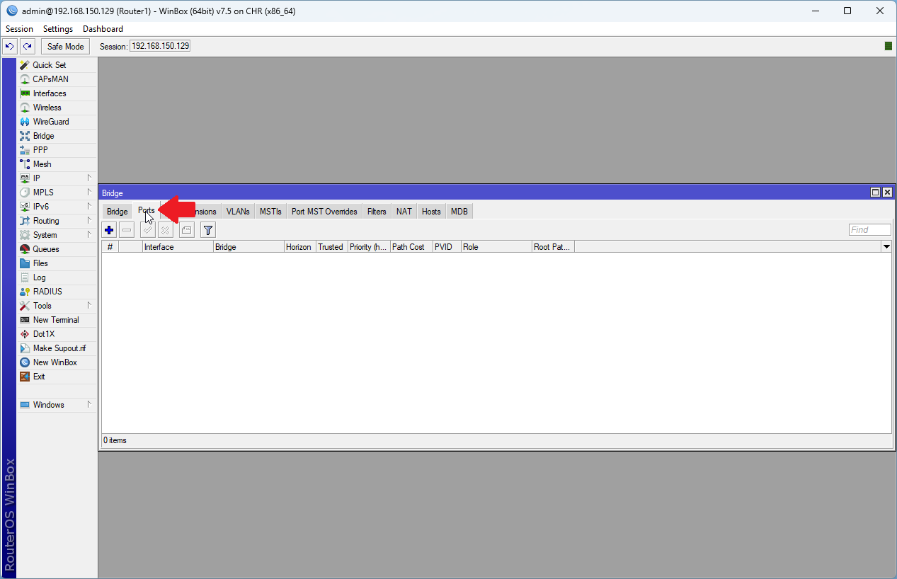
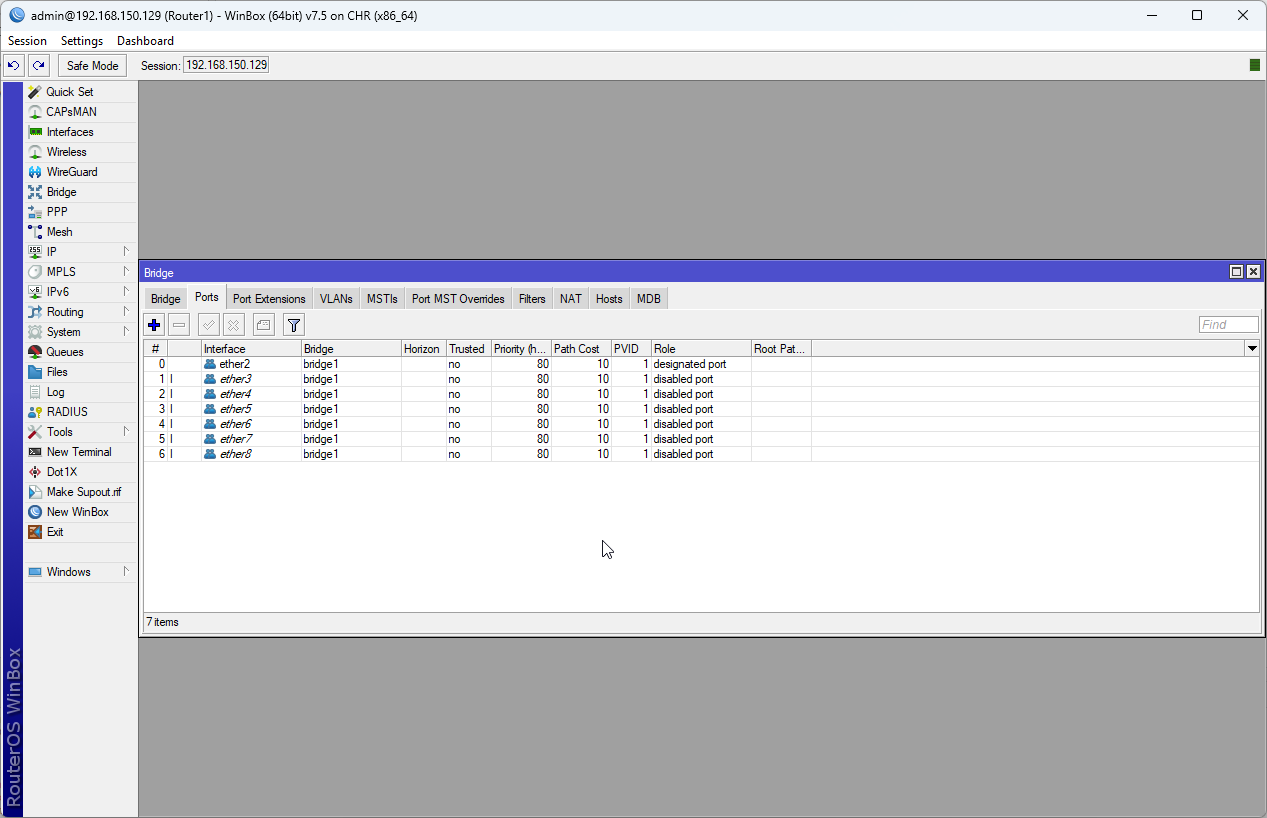
3. Next, navigate to the Ports tab on the Bridge window and click the + button to add the remaining ports on our router to the bridge interface.
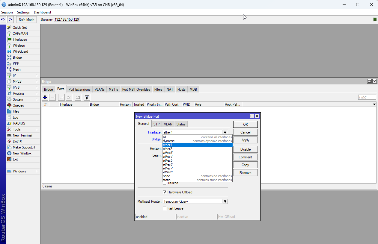
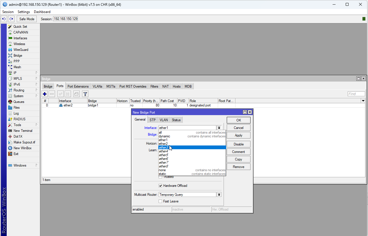
In this scenario, we are going to add ethernet ports 2-8 to our bridged interface. We will make the bridged interface our LAN. Ethernet port 1 will be used for our WAN interface, so we do not want to add it to our bridge. To add the first port (ether2), under the interface dropdown, select ether2 and under bridge, select bridge1 and then hit OK. Repeat this step for ether3 - ether8.
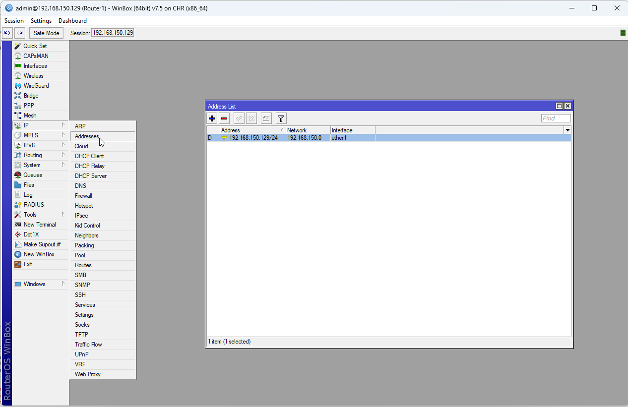
3. Next, we will assign an IP address to our bridged interface, which will serve as the local LAN IP address for the router. Select IP -> Addresses from the left hand menu to bring up the address list window. To this, we are going to add another IP address of 192.168.1.1 and assign the address to the bridge interface that we just created. Click the + in the Address List window to add a new IP address.
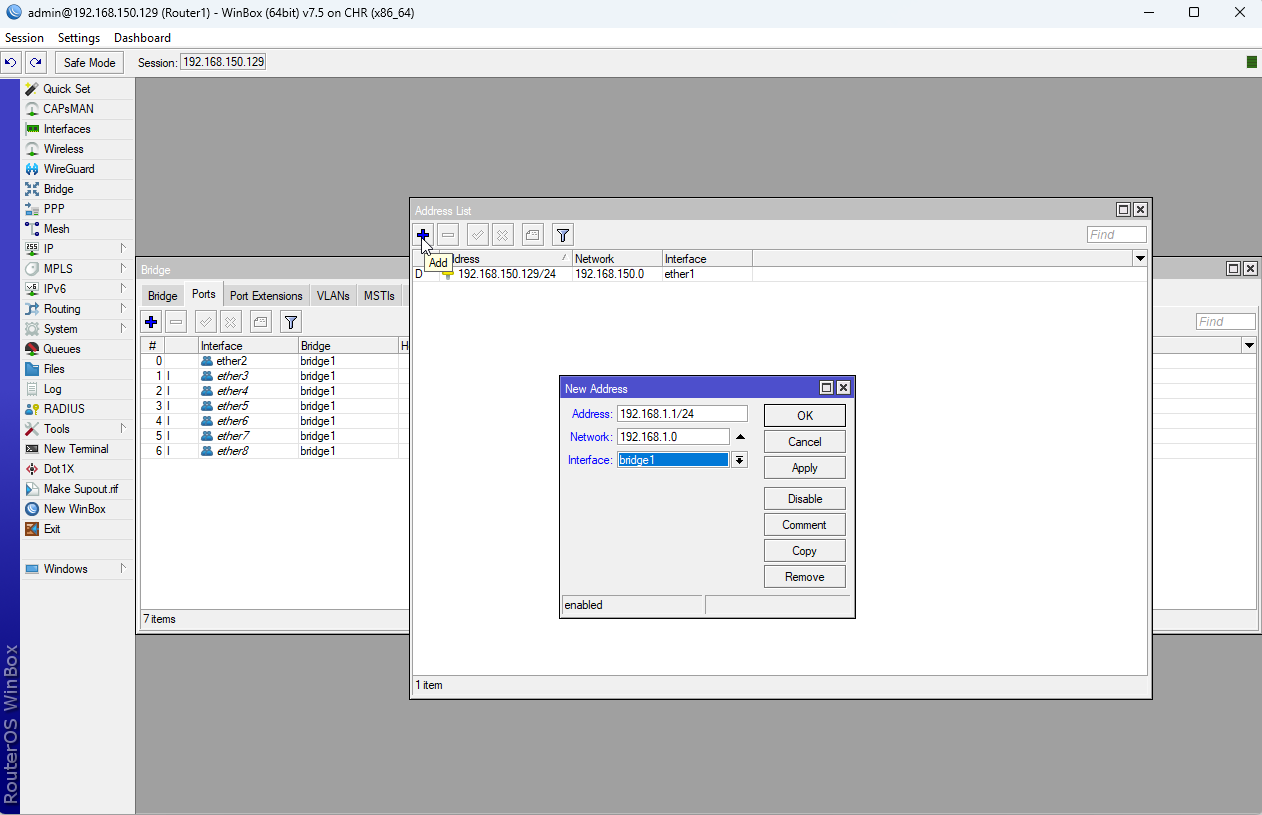
Enter the following settings in the New Address window that appears:
Address: 192.168.1.1/24
Network: 192.168.1.0
Interface: bridge1
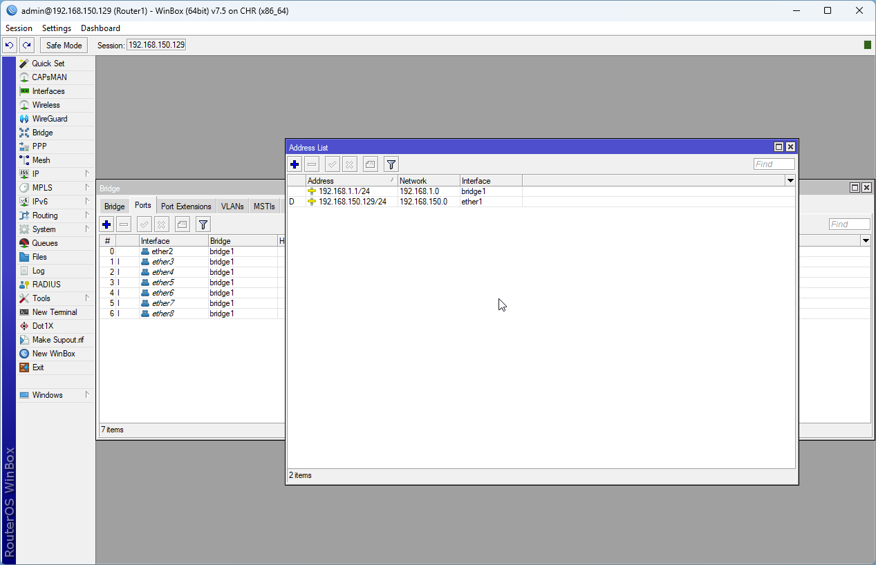
These settings denote that our router internal LAN IP address on this bridge will be 192.168.1.1. Our subnet mask (/24) is 255.255.255.0, meaning that our private IP address range will be 192.168.0.0 - 192.168.1.255. (The 192.168.1.0 network will provide 254 usable IPs in the 192.168.1.0/24). The broadcast address is the last address in the subnet, meaning our broadcast address will be 192.168.1.255. (In technical terms, In IPv4, it is obtained by setting all host bits in the subnet mask to 1 and applying it as a bitwise OR operation with the network address.). Instead of applying the setting to a specific physical interface (ether2 - ether8), we apply the configuration to our virtual bridge interface bridge1 which will span all of the remaining physical interfaces, ether2 - ether8, so all of these interfaces will be part of this network.
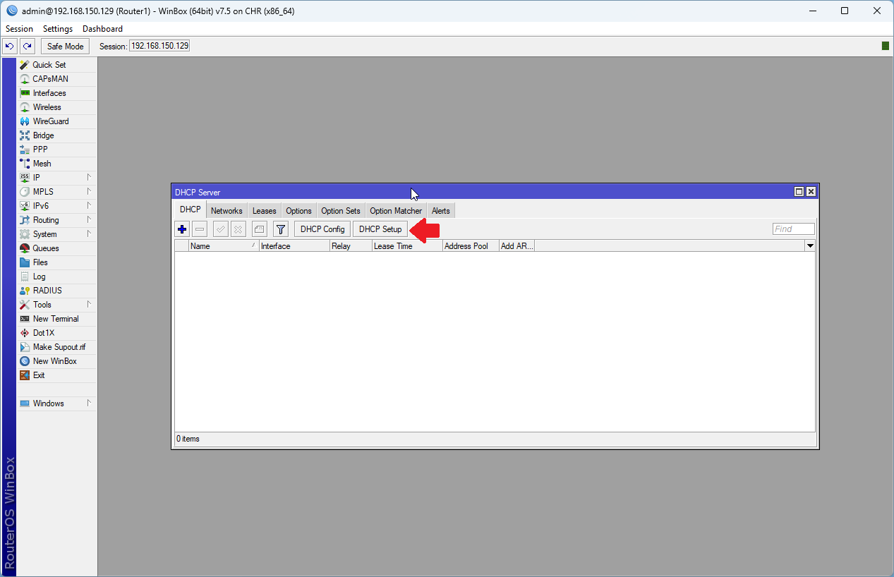
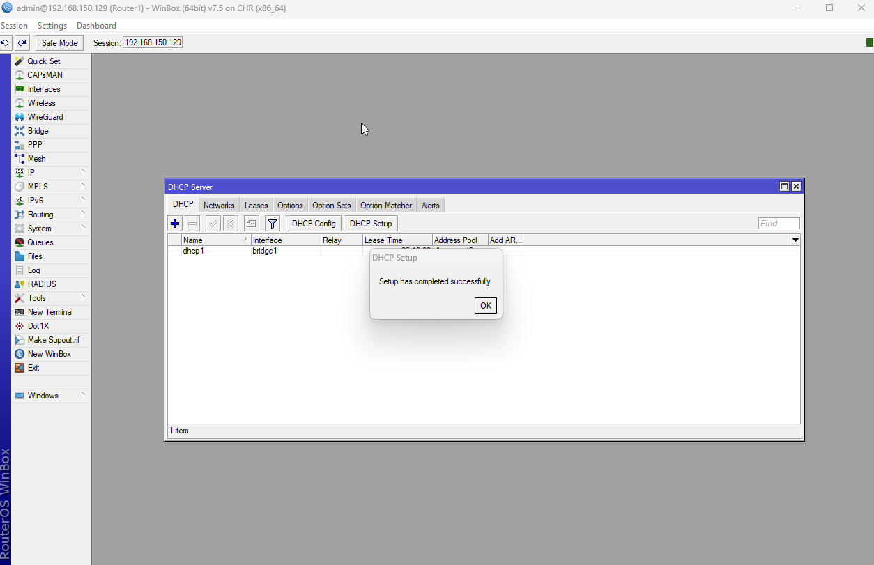
Next, we are going to create a DHCP server, which will allow us to auto-assign IP addresses to our clients. To add a new DHCP server, select IP -> DHCP Server from the left hand menu to bring up the DHCP servers window.

4. The easiest way to create a DHCP server is to use the DHCP Setup wizard to navigate us through the creation of the new server. Click the DHCP Setup button at the top.
Go ahead and apply the changes by clicking the Apply Configuration button.
5. When prompted which interface to run the DHCP server on, select bridge1 as shown and hit Next to continue.

6. We are going to use the suggested DHCP Address space 192.168.1.0/24. Hit Next to continue.

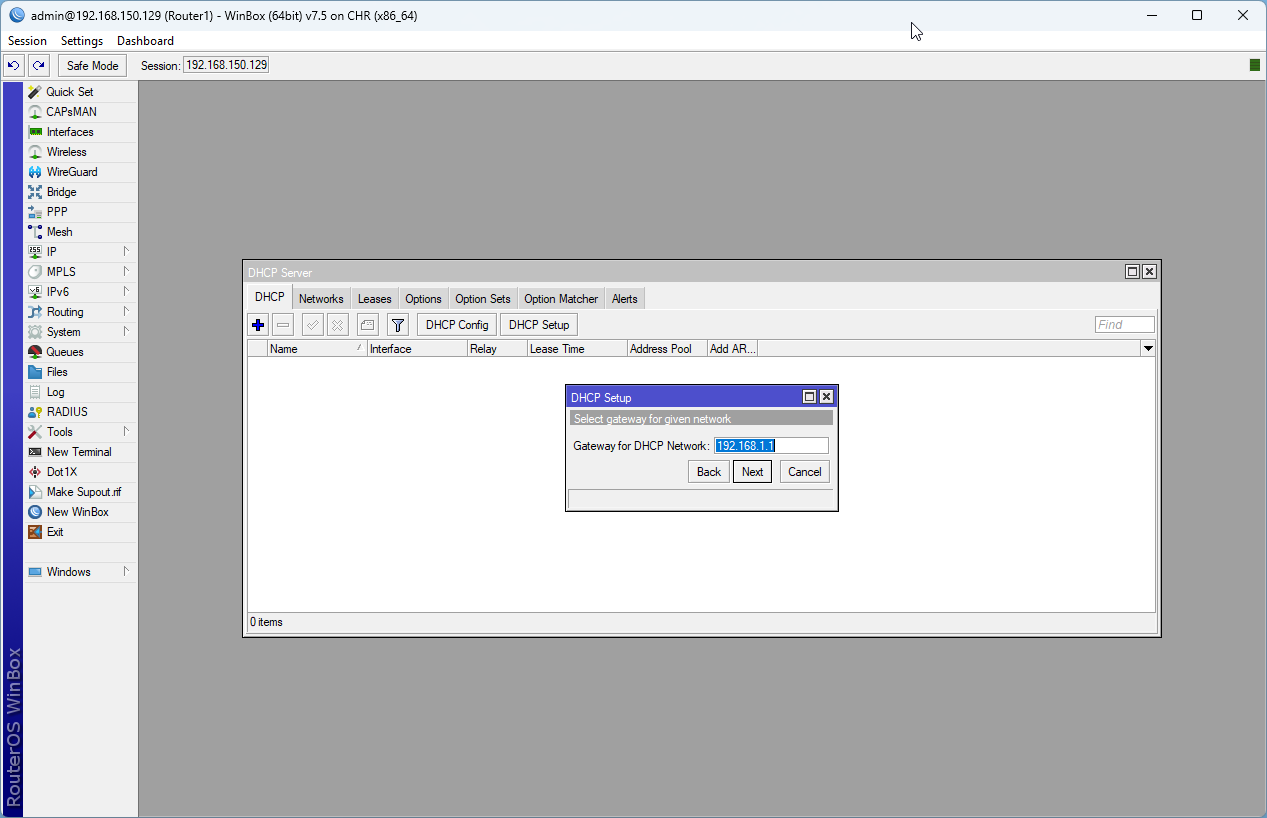
7. Next, when prompted for the DHCP gateway for our network, leave it at 192.168.1.1. Our router will act as the gateway for our network. Hit Next to continue.
8. Next, we need to assign the pool of IP addresses to assign. The default is to assign 192.168.1.2 - 192.168.1.254, meaning that there are 253 available addresses that can be assigned to clients. Click Next to continue.

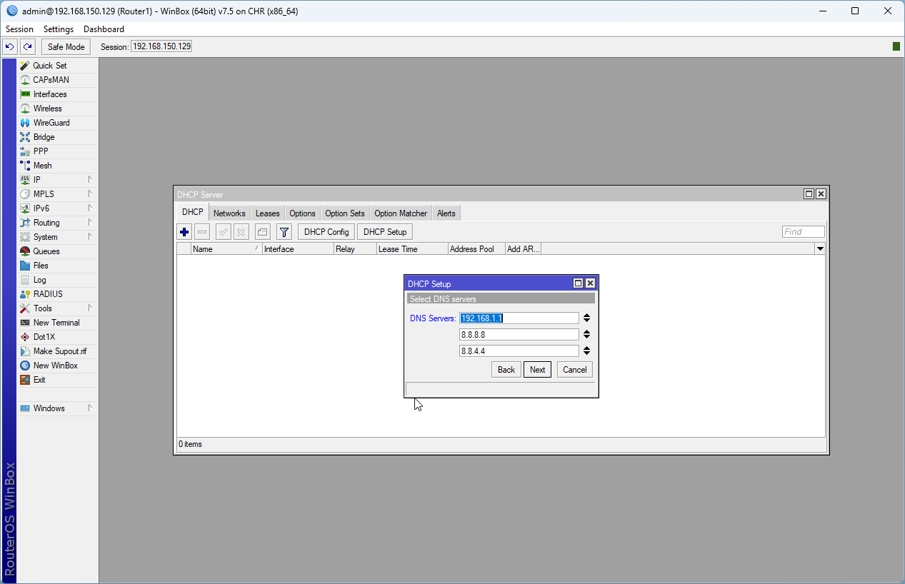
9. Next, we need to assign DNS servers to our DHCP server. This will be the list of servers that are responsible for translating our hostnames (e.g. google.com, microsoft.com, mikrotikusers.com, etc..) into IP addresses. We are going to assign 3 DNS servers to our server. To assign the IP addresses, type the IP address in the DNS server input box, and you can hit the down arrow next to the input box to enter additional addresses. Enter the following three addresses and hit Next to continue.
192.168.1.1 (our router)
8.8.8.8 (google DNS server 1)
8.8.4.4 (google DNS server 2)
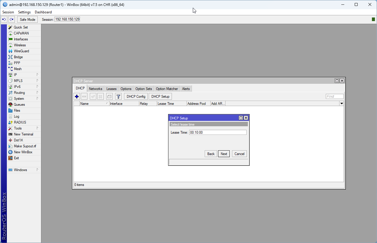
10. Next, we are going to set the DHCP lease time. DHCP lease time refers to the duration for which a device is allowed to use an IP address assigned by a DHCP (Dynamic Host Configuration Protocol) server. When a device connects to a network and requests an IP address via DHCP, the server leases (or lends) an IP address to the device for a specific period of time. During this lease period, the device can use the IP address to communicate on the network. When the lease expires, if the device that requested the IP address has not renewed its lease, that IP address becomes available. The default lease for this MikroTik device is 10 minutes. We can leave that as is for right now and hit Next to continue.
Step 6: Test if the node can access the Internet
- Right click on the VPCS node and choose Console from the pop-up menu.
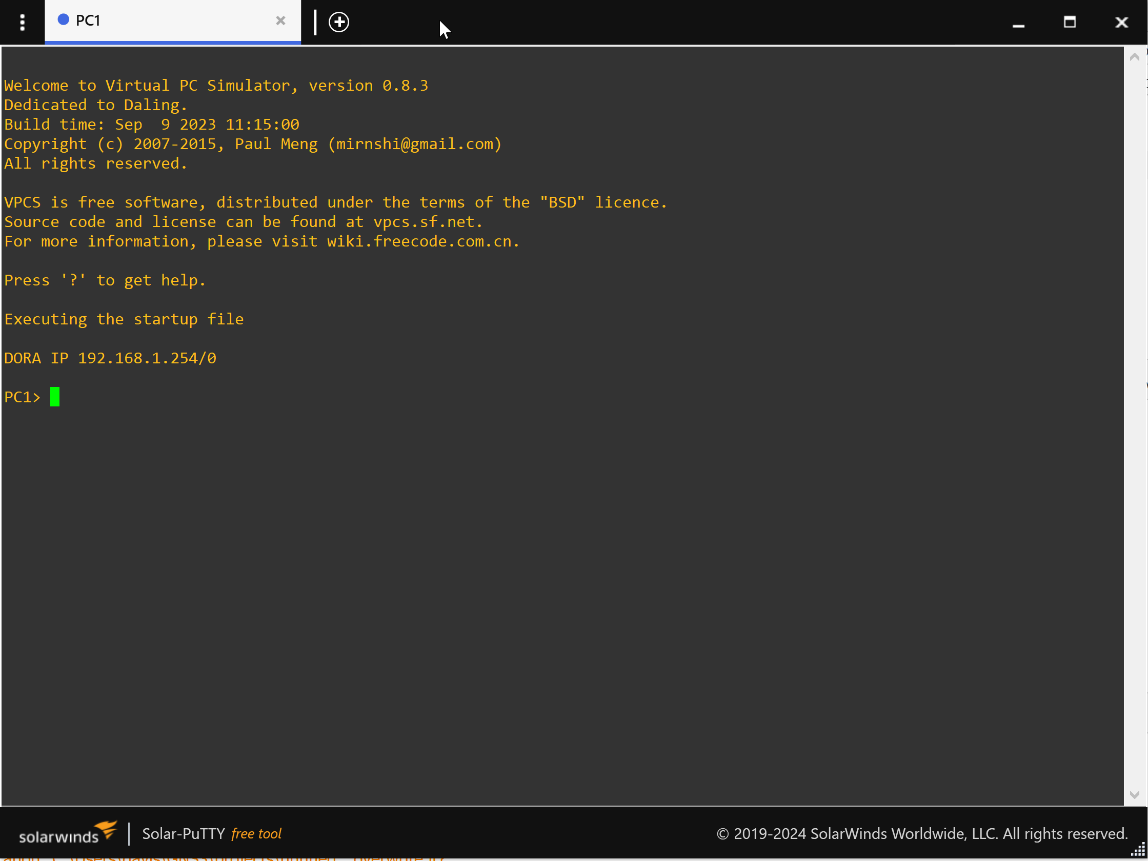
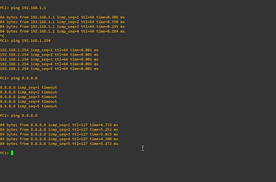
2. Lets see if we can ping the machine itself. Type the following command:
ping 192.168.1.254
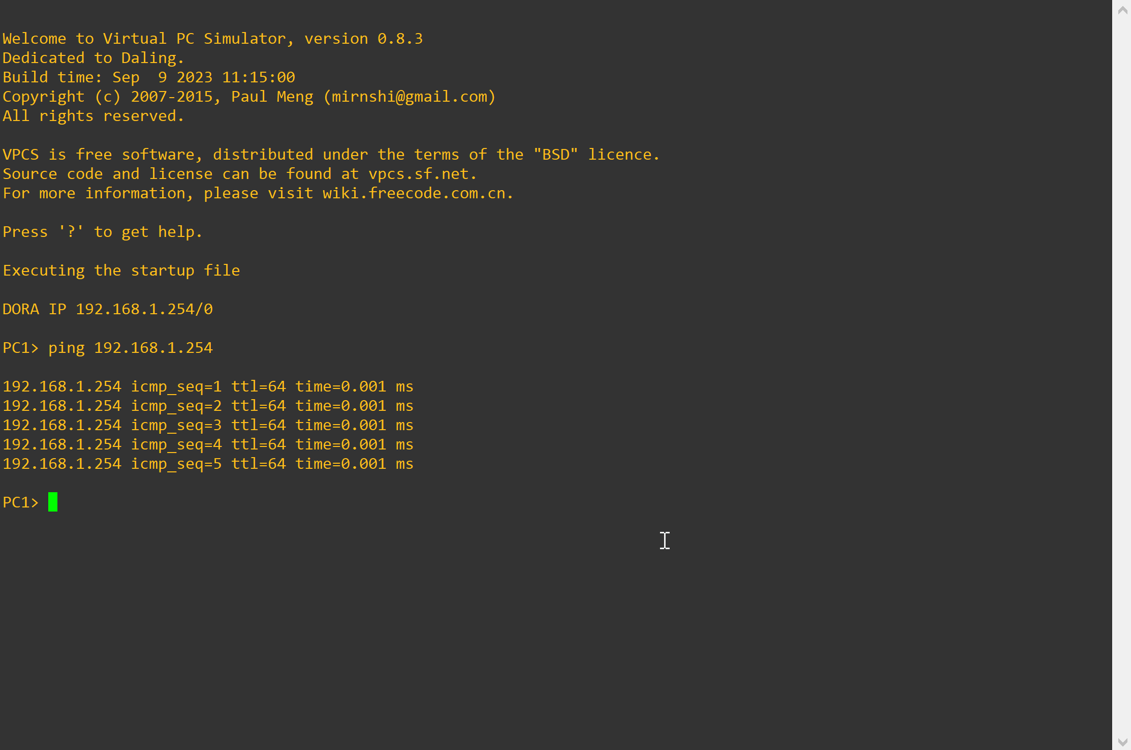
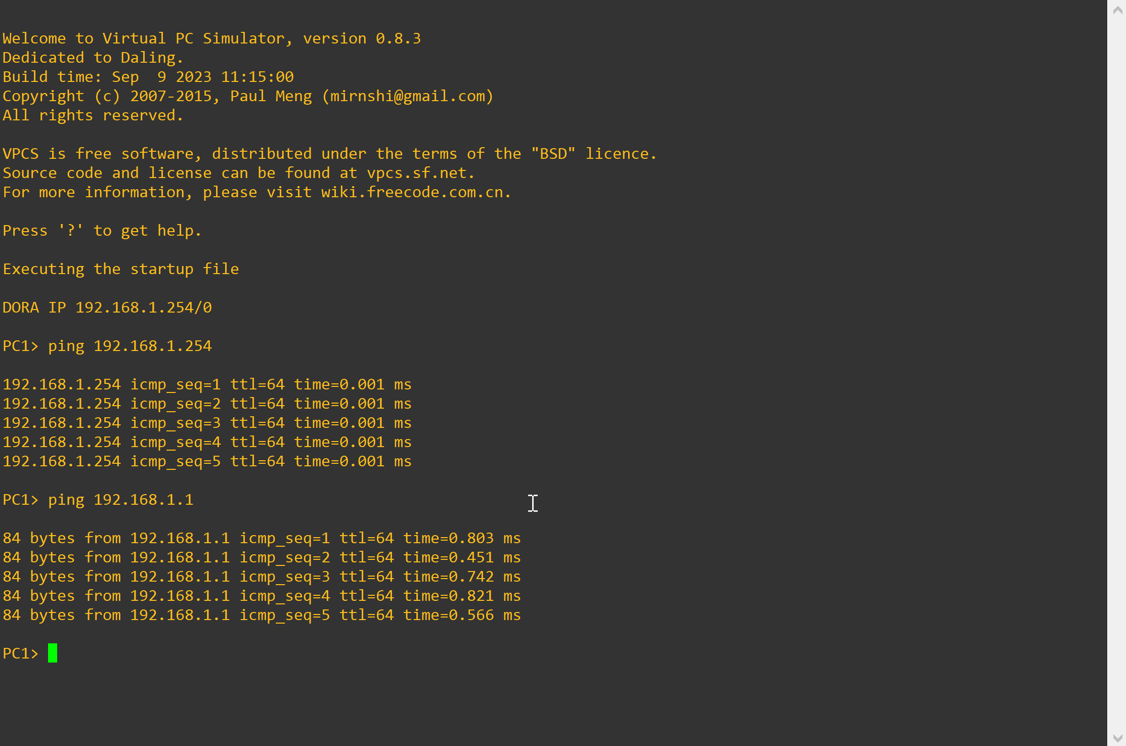
3. Let's see if we can ping the router. Type the following command:
ping 192.168.1.1
4. Let's see if we can now ping outside our network. We are going to ping the google DNS server (8.8.8.8)
ping 8.8.8.8
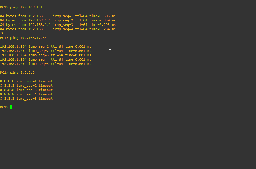
The issue here is that we have not set up NAT to perform our internal to external IP translation, so our client is not able to currently access any services outside of our internal network. To set up our NAT, we are going to do this in our firewall. Select IP -> Firewall and then hit the NAT tab.
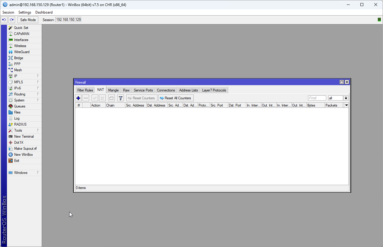
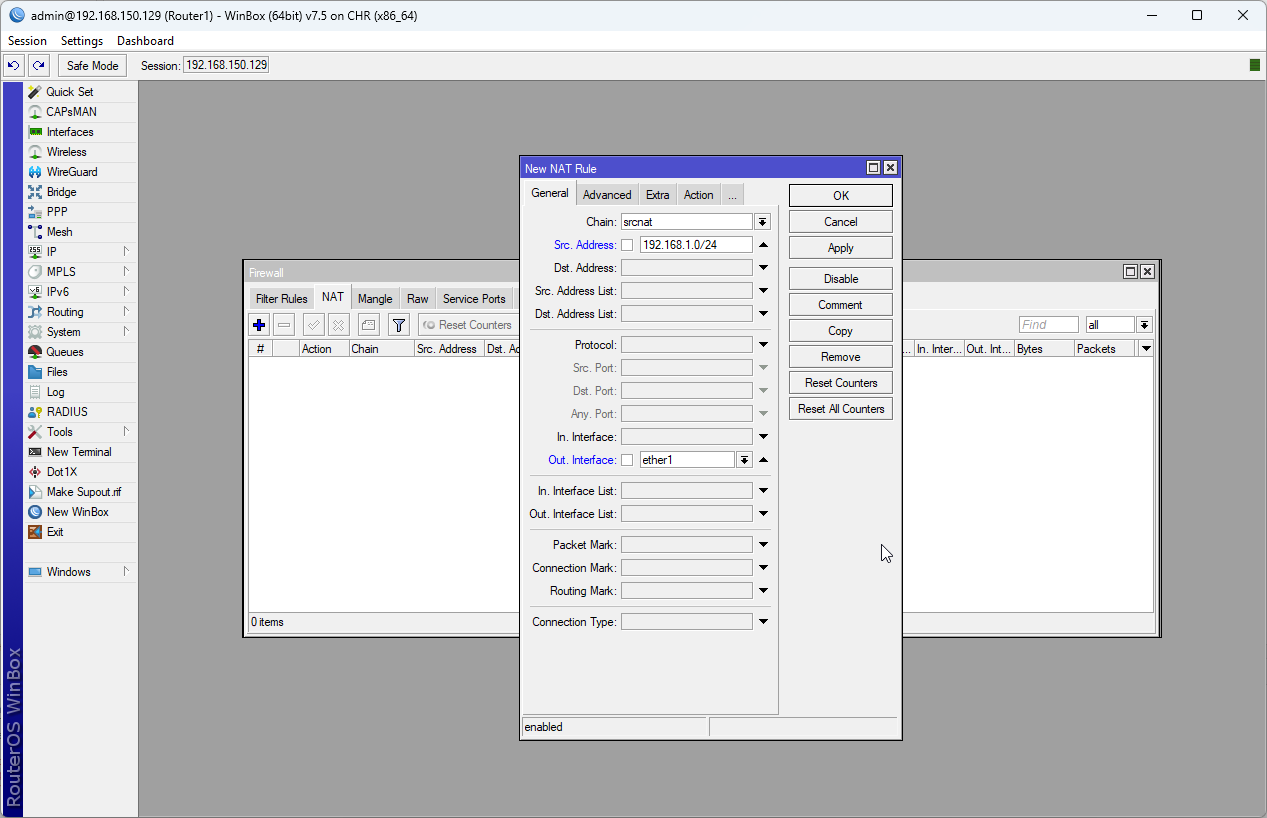
5. Let's enable NAT by setting up a rule on our firewall. To create a new rule hit the + button. We are going to set the following:
Set the chain option to srcnat
Set the Src Address option to 192.168.1.0/24
Set the Out Interface to ether1
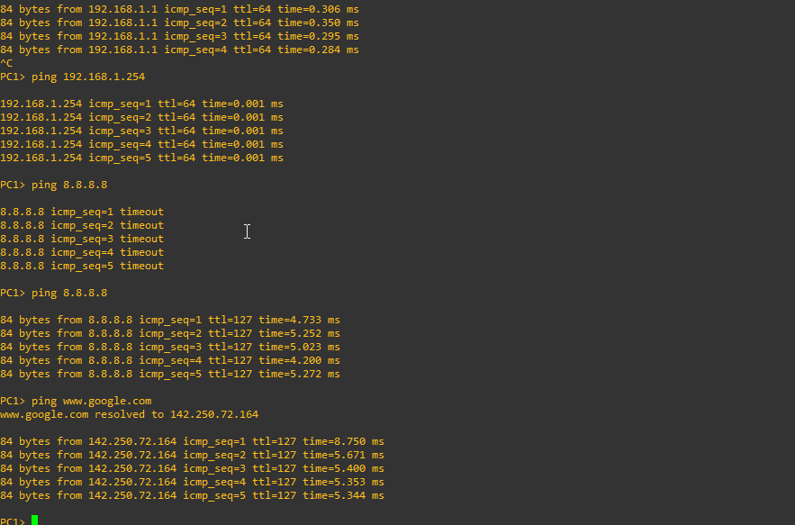
6. Navigate to the Action tab, and under action choose masquerade and hit the OK button to finish creating our new rule. Let's go back and test and see if we are able to access the Internet from our client. Type the following
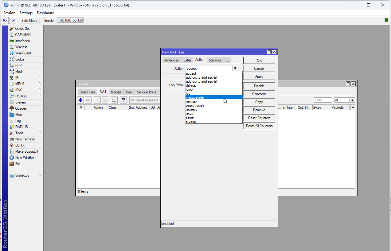
ping 8.8.8.8
Let's also see if we can access the Internet using hostnames instead of IP address. Type the following
ping www.google.com
We have successfully configured our router with essential settings such as establishing a hostname, creating a local area network, connecting a client, and verifying internet connectivity from our host. This lab setup will serve as the foundation for our upcoming series of experiments.