Lab 2.1 - First Interactions with the MikroTik Router

Lab 2.1 - First Interactions with the MikroTik Router
Photo by rivage / Unsplash
💡
Goals of this Lab:1. Create a new GNS3 workspace2. Login to the router3. Create a new password for the router4. Set the router hostname5. Create a local network6. Test if the node can access the Internet7. Reset the router configuration

Step 1: Create a new GNS3 workspace

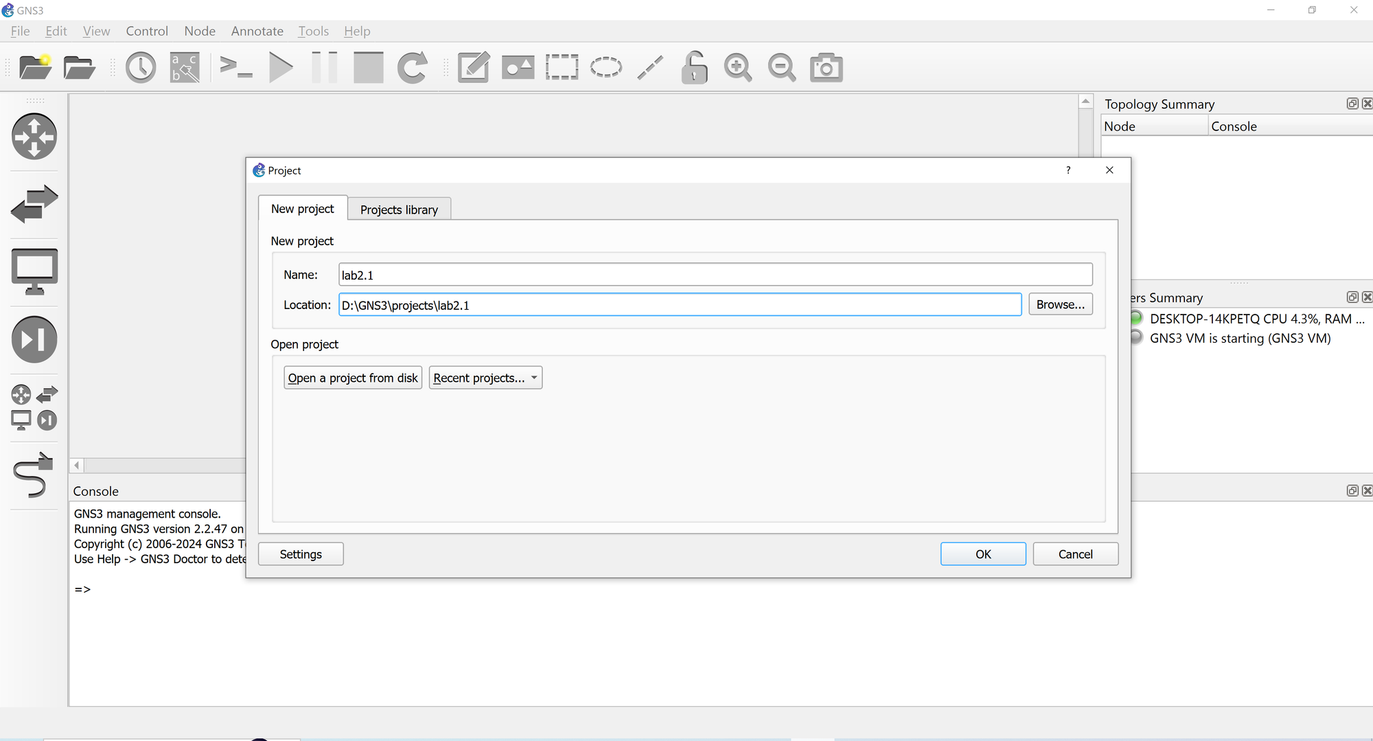
  1. Open GNS3. When the project screen appears, enter the new project details as follows. If the screen doesn't open, go to File -> New Blank Project (or hit CTRL+N on your keyboard). Hit OK to continue.
GNS3 - the graphical network simulator

To this workspace, we are going to add a Cloud node, a MikroTik CHR node, and a VPCS node. The Cloud node will enable us to access the workspace nodes from our local machine, the MikroTik CHR node will provision a router for us, and the VPCS node will provision a client that we can use to test our setup.

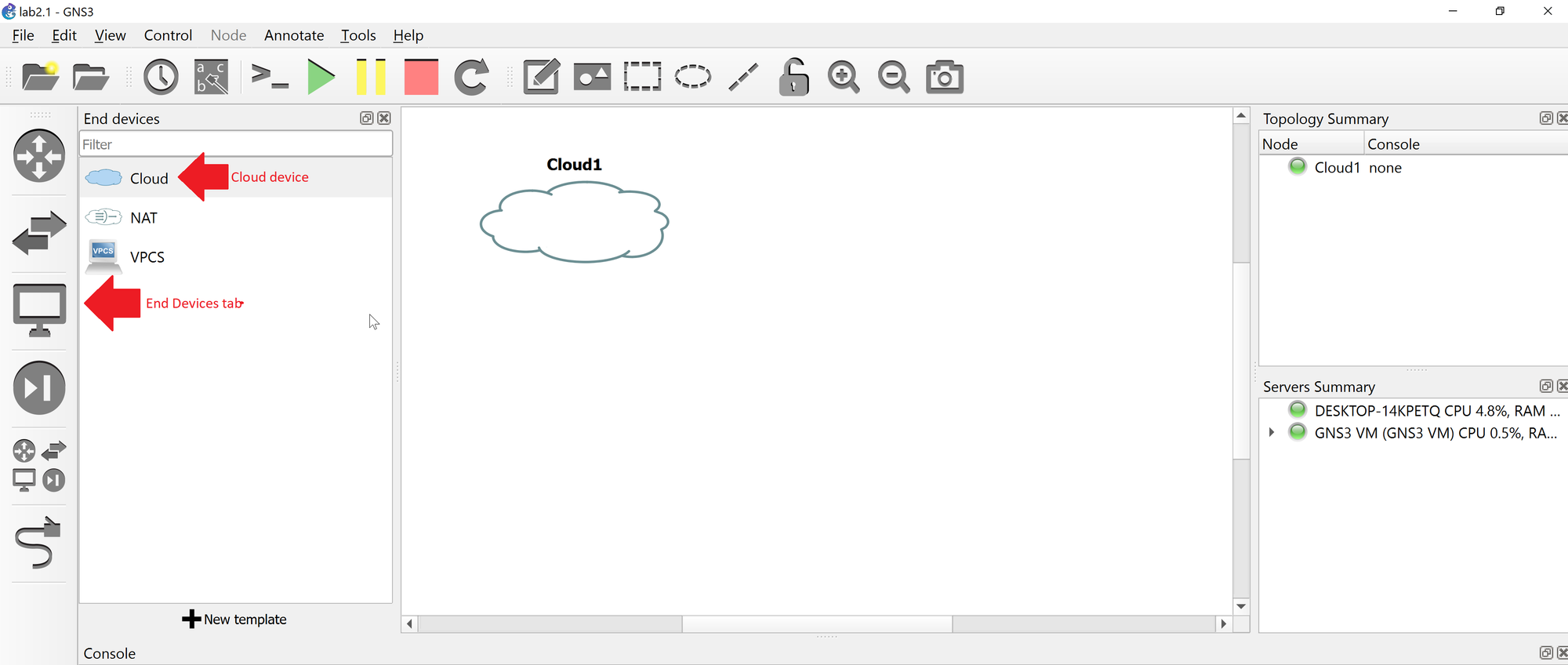
2. Let's add the Cloud node. Under the End Devices tab, select the Cloud node and drag it onto the blank workspace area. You should end up with something similar. When asked to choose a server, select GNS3 VM from the list and hit the OK button.

Adding cloud device to workspace

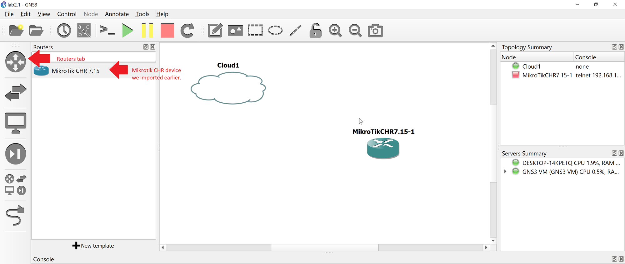
3. Next, add a MikroTik CHR node to the workspace. Under the Routers tab, select the MikroTik CHR router device we imported earlier and drag it onto the blank workspace area. Again, choose GNS3 VM as our server when prompted.

4. Next, add a VPCS node to the workspace. This is a console device that will let us test connectivity for the device. Again, Under the End Devices tab, this time, select the VPCS node and drag it onto the blank workspace area. You should end up with something similar. When asked to choose a server, select GNS3 VM from the list and hit the OK button. Your workspace should resemble the following.

VPCS node added.

5. Next we need to create the connections between the devices. This simulates the physical ethernet connections that we would use to connect the devices to the Internet. We are going to connect the cloud eth-1 device to the CHR's ether1 and we will connect port 2 on the router (ether2) to the VPCS node (eth-0)

Connect the eth-0 node from the Cloud1 node to the ether1 interface of the CHR device.
Connect the Ethernet0 interface of the VPCS node to the ether2 interface of the CHR device

6. Notice the green dot next to the Cloud1 interface and the red dots next to the CHR device and the VPCS device. This is indicative of the node status. Red dots indicate that the interface is inactive, and in this instance, it is because the devices are currently not running. Green dots indicate that the interface is active. Next we are going to start the CHR router and the VPCS device. We are going to start the router first, and then we have one additional configuration we need to make to the VPCS device before we start it. Right click on the MikroTik CHR node in our workspace and select Start from the pop-up menu that appears.

Starting the CHR device. Right click on the node and select Start from the menu that appears.
Notice when we started the CHR device, both interfaces (ether1 and ether2) are now green.

7. We are going to start the VPCS device next, but before we do, we want to enable DHCP on the VPCS node, so that the virtual PC will be able to grab an IP address from the router. To make this change, right click the VPCS node and select Edit Config from the pop-up menu that appears.

8. Uncomment the dhcp line from the config as follows and then save the config by hitting the Save button at the bottom of the screen.

We are now going to start the VPCS device. We can also start nodes by right-clicking them in the Topology Summary window and select Start from the menu that appears.

Right-Click the node in the Topology Summary window and select Start from the menu that appears. This is the same as right clicking the node on the Workspace and selecting Start

Your network topology should resemble the following screen. We are going to use this basic setup for the first few exercises.

Step 2: Log In to the Router (Console)

We are going to log in to the router using the GNS3 console. This will allow us to see pertinent information about the router, such as the IP address we will use to access the router.

  1. Right click on the CHR node and select Console from the pop-up menu that appears
Starting the console

2. When the console appears, log in to the console using the default username (admin) and password (hit the ENTER button - there is no password assigned by default).

3. When you have logged in for the first time, you will be asked to accept the license agreement. If you've never viewed the CHR license, you can type Y to view the license agreement or N to skip. We are going to skip viewing the license agreement (you should read this at some point)

Logged into the MikroTik device for the first time.

4. You will be prompted to set a password for your console. In real-world usage, we would want to set a complex hard-to-guess password, but for practice with our console, we can use a much simpler password. Set a password for the device and hit ENTER, and when prompted, re-enter the password and ENTER again.

We are logged into the MikroTik console

We need to get the IP address of the MikroTik interface so that we can log into the router. An easy way to get the IP address of the public interface (in this case our public interface is ether1), type the following two commands in the console to get the IP address.

:global addr [/ip address get [find interface="ether1"] address]
:put $addr
Retrieving the public interface of the Cloud address

From the image, you can see our IP address is 192.168.154.131. The /24 denotes the subnet (255.255.255.0)

Knowing our IP address, we are going to log into our router using the Web interface. Open your web browser, and enter the IP address of your router. It should bring up the router login screen. At this screen you will enter the password that you created earlier, and hit the Login button to log in to your router.

Accessing the MikroTik router using the web interface
MikroTik web interface

Step 3: Change the router password

  1. We are going to change the password of the router using the web interface. To do so, navigate to the bottom of the quick set password page, and hit the Password... button. Upon doing so, you will be taken to the password change page and asked to enter the old password, a new password, and retype the new password as shown below and hit the Change Now button.
Change the password

Step 4: Change the Router Hostname

  1. The default hostname for the MikroTik router is MikroTik. We are going to change the hostname for the router to Router1. To do so from the web interface, open the Quick Set page and under System -> Router Identity change the name from Mikrotik to Router1 as shown below and click the Apply Configuration button.
Changing the default hostname of the router

Step 5: Create a local network and test

Our next step is to create a local area network, connect our VPCS device to the local network, and then test our VPCS to see if it has an IP address and if it is able to access the Internet.

  1. Navigate to the Quick Set page. Under the Local Network header, we are going to make the following configuration changes.

    IP Address: 192.168.1.1
    Netmask: 255.255.255.0 (/24)
    Bridge all LAN ports: (enable)
    DHCP Server: (enable)
    DHCP Server Range: 192.168.1.2-192.168.1.254
    NAT: (enable)

What we have done is set the router LAN accessible IP address to 192.168.1.1, configured a LAN network with DHCP auto IP address assignment of up to 254 nodes (192.168.1.2 - 192.168.1.254). We also bridged the remaining interfaces on the switch (ether2-ether8) into a single logical interface. What this does is any data packets received on any one of the bridged interfaces are forwarded to the other interfaces in the bridge, effectively allowing us to connect devices to any one of the remaining interfaces on the router to this network. We also enabled network address translation, effectively allowing devices to communicate with the outside network and Internet while inside our private network. Your configuration should now resemble the following

Local network configuration

Go ahead and apply the changes by clicking the Apply Configuration button.

Step 6: Test if the node can access the Internet

  1. Right click on the VPCS node and choose Console from the pop-up menu.
VPCS node loaded
💡
If you discover that your VPCS node did not get an IP address as shown above, you can try to re-request an IP address using the command:ip dhcp

2. Lets see if we can ping the machine itself. Type the following command:

ping 192.168.1.254

Looks good. We can ping the machine itself using the IP address it was assigned.

3. Let's see if we can ping the router. Type the following command:

ping 192.168.1.1

Looks good. We can ping the router using the IP address it was assigned.

4. Let's see if we can now ping outside our network. We are going to ping the google DNS server (8.8.8.8)

ping 8.8.8.8

Success! We are able to access the outside world

Step 7: Reset the router configuration

Go back to the router web interface

  1. On the Quick Set configuration page, in the bottom right corner, click the Reset Configuration button.
Reset Configuration

2. Click the Reset Configuration button here to reset the router.

3. When prompted, click OK to confirm the reset and reboot the router.