Lab 5.2 Configuring SSTP Site-to-Site VPN

Lab 5.2 Configuring SSTP Site-to-Site VPN
Configuring SSTP Site-to-Site VPN

In part 2 of our series, we delve into the configuration of SSTP, or Secure Socket Tunneling Protocol, which is considered a much safer method of encrypting traffic between two endpoints as opposed to PPTP. We are going to use a similar setup as to our previous example configuring PPTP. It is just as easy to set up SSTP as was PPTP, and SSTP should be considered the preferred method over PPTP.

What is SSTP?

SSTP, or Secure Socket Tunneling Protocol, is a VPN (Virtual Private Network) protocol developed by Microsoft. It’s designed to secure communications between a client and a server by tunneling communication through HTTPS (HTTP over SSL/TLS), which is the same encryption technology used for secure web browsing.

Key Features of SSTP:

  1. Encryption and Security: SSTP uses SSL/TLS for encryption, which is a robust and widely trusted method. This provides a high level of security, protecting data from eavesdropping and tampering.
  2. Firewall and NAT Traversal: Because SSTP uses HTTPS, it can easily pass through firewalls and Network Address Translation (NAT) devices, which can sometimes block other VPN protocols.
  3. Authentication: It supports strong authentication methods, including the use of certificates and username/password combinations.

Why SSTP is Preferred Over PPTP:

  1. Security: SSTP is generally considered more secure than PPTP (Point-to-Point Tunneling Protocol). PPTP has known security vulnerabilities and is susceptible to various attacks, whereas SSTP benefits from the strong encryption provided by SSL/TLS.
  2. Firewall and NAT Compatibility: SSTP can traverse firewalls and NAT devices more effectively than PPTP, which sometimes struggles with such network configurations.
  3. Data Integrity: SSTP ensures data integrity through SSL/TLS, reducing the risk of data corruption or manipulation during transmission.
  4. Modern Standards: SSTP aligns with modern security standards and practices, making it a more robust choice for secure communications compared to the outdated and less secure PPTP.

Overall, SSTP is a preferred choice for secure VPN connections on a MikroTik router or any other networking hardware due to its strong encryption, better firewall compatibility, and more modern security features compared to PPTP.

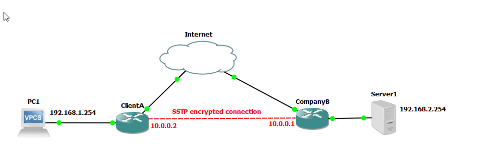
We are going to use the following network to demonstrate setup of a SSTP network. This is similar to the network we set up in a previous example using PPTP.

SSTP encrypted connection

Step 1: Set up the Client A router. To setup the MikroTik router, we are going to create a bridge interface that includes ports ether2 - ether4 with NAT (network address translation) for outbound traffic and configure ether1 as a DHCP client to obtain an IP address from our ISP (obtained from the Internet). Login to Company A router, and configure the following

# Interface Setup
/interface ethernet set [ find default-name=ether1 ] name=wan
/ip dhcp-client add interface=wan disabled=no
/interface bridge add name=bridge1
/interface bridge port
add bridge=bridge1 interface=ether2
add bridge=bridge1 interface=ether3
add bridge=bridge1 interface=ether4

/ip address
add address=192.168.1.1/24 interface=bridge1
/ip firewall nat
add chain=srcnat out-interface=wan action=masquerade

# DHCP Server
/ip dhcp-server network add address=192.168.1.0/24 gateway=192.168.1.1
/ip pool add name=dhcp_pool ranges=192.168.1.10-192.168.1.254
/ip dhcp-server add name=dhcp1 address-pool=dhcp_pool disabled=no interface=bridge1 lease-time=10m

# Set system identity
/system identity set name=ClientA

Step 2: Verify the setup on Client A router

Check the status of the DHCP client:

/ip address print

Ensure it has received an IP address from the DHCP server.

Verify the bridge ports:

/interface bridge port print

Confirm that ether2 through ether6 are listed as part of bridge1.

Check the NAT rules:

/ip firewall nat print

Ensure the masquerade rule is listed.

  1. Verify connectivity:
    • Start the VPCS device and log into the console and make sure it can access the internet.
    • Test the router’s connection to the internet using ping or other tools.

Step 3: Set up the Company B router. To setup the MikroTik router, we are going to create a bridge interface that includes ports ether2 - ether4 with NAT (network address translation) for outbound traffic and configure ether1 as a DHCP client to obtain an IP address from our ISP (obtained from the Internet). Login to Company A router, and configure the following

# Interface Setup
/interface ethernet set [ find default-name=ether1 ] name=wan
/ip dhcp-client add interface=wan disabled=no
/interface bridge add name=bridge1
/interface bridge port
add bridge=bridge1 interface=ether2
add bridge=bridge1 interface=ether3
add bridge=bridge1 interface=ether4
add bridge=bridge1 interface=ether5
add bridge=bridge1 interface=ether6
/ip address
add address=192.168.2.1/24 interface=bridge1
/ip firewall nat
add chain=srcnat out-interface=wan action=masquerade

# DHCP Server
/ip dhcp-server network add address=192.168.2.0/24 gateway=192.168.2.1
/ip pool add name=dhcp_pool ranges=192.168.2.10-192.168.2.254
/ip dhcp-server add name=dhcp1 address-pool=dhcp_pool disabled=no interface=bridge1 lease-time=10m

# Set system identity
/system identity set name=CompanyB

Step 4: Verify the setup on Company B router

Check the status of the DHCP client:

/ip address print

Ensure it has received an IP address from the DHCP server.

Verify the bridge ports:

/interface bridge port print

Confirm that ether2 through ether6 are listed as part of bridge1.

Check the NAT rules:

/ip firewall nat print

Ensure the masquerade rule is listed.

Step 5: Verify connectivity from the ClientA router to CompanyB router. Ping the ether1 interface of the CompanyB router from the ClientA router to ensure that it is reachable over the Internet (in our case simulated internet). In our scenario, the IP address for the ClientA router is 192.168.150.146 and the IP address for the CompanyB router is 192.168.150.147.

Ping CompanyB router from ClientA

To set up a SSTP VPN connection between ClientA and CompanyB routers using RouterOS 7 via the command line interface (CLI), follow these instructions.

CompanyB router:

/interface sstp-server server set enabled=yes
/ppp secret add local-address=10.0.0.1 name=clientA password=letmein profile=default-encryption remote-address=10.0.0.2 service=sstp
/ip route add disabled=no dst-address=192.168.1.0/24 gateway=10.0.0.2

ClientA router:

/interface sstp-client add connect-to=192.168.150.147 disabled=no name=sstp-out1 user=clientA password=letmein profile=default-encryption
/ip route add disabled=no dst-address=192.168.2.0/24 gateway=10.0.0.1

Verify connectivity on the server

/ppp active print
Active SSTP connection

Now, because we set up a route on both the server and the client, we should be able to ping from the client PC to the server. On the VPCS machine, issue a ping to the server. Our server is located at 192.168.2.254, but yours might be different depending on the IP address assigned to the VPCS device.

From ClientA VPCS machine

ping 192.168.2.254

If you are able to ping the client machine, then you have successfully established a SSTP VPN connection between two routers (site-to-site).

💡
Please be aware that the username and password for the gns3 project is admin/admin