Lab 5.3 Configuring L2TP/IPSec Site-to-Site VPN

Lab 5.3 Configuring L2TP/IPSec Site-to-Site VPN
Configuring L2TP/IPSec Site-to-Site VPN

In part 3 of our series, we delve into the configuration of L2TP/IPSec (Layer 2 Tunneling Protocol with Internet Protocol Security), which is also considered a safe method of encrypting traffic between two endpoints. L2TP/IPsec is versatile and secure but may require more complex configuration and can face issues with firewalls and NAT because it uses UDP ports and IPsec protocols that may need special handling as opposed to SSTP which operates over TCP port 443 which is commonly open and used for HTTPS traffic. Choosing between L2TP/IPsec and SSTP depends on your specific needs, including the operating systems in use, network infrastructure, and security requirements.

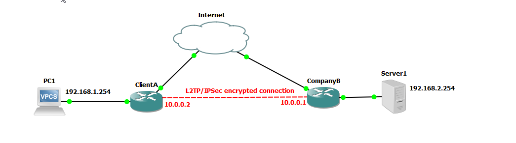
We are going to use a similar setup as to our previous example configuring PPTP and SSTP.

L2TP/IPSec encrypted connection

L2TP/IPsec:

L2TP is a tunneling protocol that encapsulates data packets for transmission, while IPsec provides encryption and authentication. Together, they create a secure VPN connection.

Benefits:

  1. Widely Supported: L2TP/IPsec is supported by many operating systems and devices, making it versatile for various environments.
  2. Encryption and Authentication: IPsec ensures strong encryption and authentication for secure data transmission.
  3. Combines Tunneling and Security: L2TP provides the tunneling, while IPsec handles the security, offering a layered approach to VPN security.

Downsides:

  1. Complex Configuration: Setting up L2TP/IPsec can be more complex than SSTP, requiring careful configuration of both L2TP and IPsec settings.
  2. Performance Overhead: The double encapsulation (L2TP + IPsec) can introduce additional latency and overhead, potentially affecting performance.
  3. Firewall and NAT Issues: L2TP/IPsec can face challenges with firewalls and NAT (Network Address Translation) because it uses UDP ports and IPsec protocols that may need special handling.

Step 1: Set up the Client A router. To setup the MikroTik router, we are going to create a bridge interface that includes ports ether2 - ether4 with NAT (network address translation) for outbound traffic and configure ether1 as a DHCP client to obtain an IP address from our ISP (obtained from the Internet). Login to Company A router, and configure the following

# Interface Setup
/interface ethernet set [ find default-name=ether1 ] name=wan
/ip dhcp-client add interface=wan disabled=no
/interface bridge add name=bridge1
/interface bridge port
add bridge=bridge1 interface=ether2
add bridge=bridge1 interface=ether3
add bridge=bridge1 interface=ether4

/ip address
add address=192.168.1.1/24 interface=bridge1
/ip firewall nat
add chain=srcnat out-interface=wan action=masquerade

# DHCP Server
/ip dhcp-server network add address=192.168.1.0/24 gateway=192.168.1.1
/ip pool add name=dhcp_pool ranges=192.168.1.10-192.168.1.254
/ip dhcp-server add name=dhcp1 address-pool=dhcp_pool disabled=no interface=bridge1 lease-time=10m

# Set system identity
/system identity set name=ClientA

Step 2: Verify the setup on Client A router

Check the status of the DHCP client:

/ip address print

Ensure it has received an IP address from the DHCP server.

Verify the bridge ports:

/interface bridge port print

Confirm that ether2 through ether6 are listed as part of bridge1.

Check the NAT rules:

/ip firewall nat print

Ensure the masquerade rule is listed.

  1. Verify connectivity:
    • Start the VPCS device and log into the console and make sure it can access the internet.
    • Test the router’s connection to the internet using ping or other tools.

Step 3: Set up the Company B router. To setup the MikroTik router, we are going to create a bridge interface that includes ports ether2 - ether4 with NAT (network address translation) for outbound traffic and configure ether1 as a DHCP client to obtain an IP address from our ISP (obtained from the Internet). Login to Company A router, and configure the following

# Interface Setup
/interface ethernet set [ find default-name=ether1 ] name=wan
/ip dhcp-client add interface=wan disabled=no
/interface bridge add name=bridge1
/interface bridge port
add bridge=bridge1 interface=ether2
add bridge=bridge1 interface=ether3
add bridge=bridge1 interface=ether4
add bridge=bridge1 interface=ether5
add bridge=bridge1 interface=ether6
/ip address
add address=192.168.2.1/24 interface=bridge1
/ip firewall nat
add chain=srcnat out-interface=wan action=masquerade

# DHCP Server
/ip dhcp-server network add address=192.168.2.0/24 gateway=192.168.2.1
/ip pool add name=dhcp_pool ranges=192.168.2.10-192.168.2.254
/ip dhcp-server add name=dhcp1 address-pool=dhcp_pool disabled=no interface=bridge1 lease-time=10m

# Set system identity
/system identity set name=CompanyB

Step 4: Verify the setup on Company B router

Check the status of the DHCP client:

/ip address print

Ensure it has received an IP address from the DHCP server.

Verify the bridge ports:

/interface bridge port print

Confirm that ether2 through ether6 are listed as part of bridge1.

Check the NAT rules:

/ip firewall nat print

Ensure the masquerade rule is listed.

Step 5: Verify connectivity from the ClientA router to CompanyB router. Ping the ether1 interface of the CompanyB router from the ClientA router to ensure that it is reachable over the Internet (in our case simulated internet). In our scenario, the IP address for the ClientA router is 192.168.150.146 and the IP address for the CompanyB router is 192.168.150.147.

Ping CompanyB router from ClientA

To set up a L2TP/IPSec VPN connection between ClientA and CompanyB routers using RouterOS 7 via the command line interface (CLI), follow these instructions.

CompanyB router:

For this configuration, we are going to use IPSec and set up an IPSec secret password secret. For production usage, you would use a much more secure secret.

/interface l2tp-server server set enabled=yes ipsec-secret=secret use-ipsec=required
/ppp secret add local-address=10.0.0.1 name=clientA password=letmein profile=default-encryption remote-address=10.0.0.2 service=l2tp
/ip route add disabled=no dst-address=192.168.1.0/24 gateway=10.0.0.2

ClientA router:

/interface l2tp-client add connect-to=192.168.150.147 disabled=no ipsec-secret=secret name=l2tp-out1 user=clientA password=letmein profile=default-encryption
/ip route add disabled=no dst-address=192.168.2.0/24 gateway=10.0.0.1

Verify connectivity on the server

/ppp active print

Now, because we set up a route on both the server and the client, we should be able to ping from the client PC to the server. On the VPCS machine, issue a ping to the server.

Active L2TP connection

Our server is located at 192.168.2.254, but yours might be different depending on the IP address assigned to the VPCS device.

From ClientA VPCS machine

ping 192.168.2.254

If you are able to ping the client machine, then you have successfully established a SSTP VPN connection between two routers (site-to-site).

💡
Please be aware that the username and password for the gns3 project is admin/admin