Configure DHCP Services

Dynamic Host Configuration Protocol (or DHCP for short) is a network management service that is used to automatically assign IP addresses to devices attached to the network.

The goal of this tutorial is to:

Explain what DHCP is and why we use it
Create a bridge interface (bridge1)
Assign ports 2-8 of the device (ether2 - ether8) to the bridge
Configure an IP address for the bridge interface
Assign DHCP to the bridge interface
Connect a device to any port on the bridge interface, and we should get an IP address assigned to us from the DHCP server.

Why do we use DHCP?

Every device that attaches to our network is going to need an IP address. There are two ways that we can go about assigning an IP address to a device. We can either assign them on the client-end, which means that we have to have the device in our possession, or we can tell our network to assign an address to a client once they join the network. If we assign an IP address to the device from the network side, we can either assign a device a specific IP address to use, or we can configure our network to assign the device the first available address from a pool, or group of addresses we designate.  

Sometimes, configuring IP addresses from the client side is impractical. Think of, a college campus, for example where you might have hundreds or even thousands of devices attaching and detaching from a network. Imagine the headache and the logistics of having to physically touch every single device or having to devise some way of instructing the end-user how to configure the device and what if they happen to misconfigure the device? Or imaging having to keep track of assigned IP addresses and knowing which ones are used and which ones are available and making sure that you don't assign the same IP address to multiple devices or if someone misconfigures their end device and uses an IP address that belongs to another device. These two scenarios highlight issues that are mitigated with using DHCP services.

What is DHCP?

DHCP is a service that you establish on your router, that when a device attaches to the network, that device is auto-assigned an IP address from a pool of available address that have been made available. The client only needs to join the network to get the device – there is no configuration on the client side that is needed for this to work. Everything is handled from the network side and assuming the DHCP services have been setup correctly, results in much less work from the network administrators and no work needed from the client.

There are two types of DHCP IP assignments possible. If you assign a device the same IP address no matter how or when the device connects, this is called static IP address assignment, given that the address doesn't change. However, if you simply wish for a client to be assigned an address from a pool of addresses without regard to which specific address, and you do not care if that devices gets the same address every time the device connects, that is called dynamic IP address assignment.

When would you use static vs dynamic IP address assignment. When you have a device that needs to be reachable at the same IP address, you would want to assign that device a static IP address. For example, say you have a printer on the network with an IP address of 192.168.1.10. You would want to make sure that whenever data is sent to that IP address, that the printer is the the device on the receiving end that is responding. You wouldn't want another device on the network to accidentally grab this address, because then jobs sent to the printer might no longer be able to find the printer on the network because its address may have changed. A good rule of thumb is that if you have a device on the network that provides a service and needs to be reachable by other devices, assign it a static IP address. If the device does not need to be reachable by other devices, then a dynamic IP address should suffice.

We are going to configure our router to provide DHCP addresses to clients.  Let's start with our previous example.
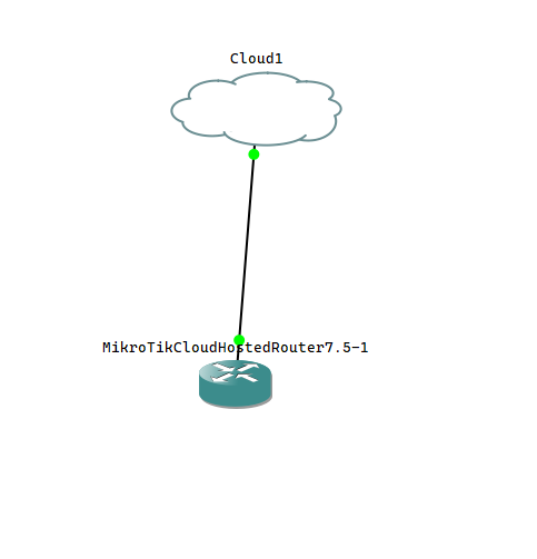
?
Before we start configuring DHCP services, we are going to expand the number of ethernet ports available on our virtual device. If you are using a physical device to follow this tutorial, you can safely ignore this comment and the next step. By default, when you add a router to your project, that device will come initialized with 2 ethernet ports, ether1 and ether2. We are going to expand the device to 8 ports.

Step 1: Before we can modify our network device, we need to remove the link between the cloud device and the router. We will put it back, but there currently exists a limitation that you cannot expand the device if there are any devices attached to it.

Right click on the link (the line between the cloud and the router device) and click delete. This will remove the link between the router and the cloud and  allow us to expand the number of network ports the device can support. Right click on the router device and click Configure. Select the Network tab and change the number of adapters from 2 to 8 and click Ok. Click the Add a Link tab on the GNS3 left menu bar and re-establish the link between the cloud and the MikroTik Router. If you are successful, you should now notice that the MikroTik router has 8 available interfaces, ether1 to ether8.

Next, we are going to log into the router and create a bridge interface for ports 2-8. A bridge allows us to create a primary interface with one or more physical interfaces grouped within that allows us to treat the group as a single unit. We can then apply a configuration to the bridge interface that will then be shared by any device connected to any of the interfaces in the group. Instead of applying IP address(es) to ether2 to ether8, we are going to create a bridge interface (bridge1) and assign ether2 to ether8 to that bridge. We will then assign an IP address to bridge1, and then configure the bridge to use DHCP to assign IP addresses to connected devices.

In summary,

+ Create a bridge interface (bridge1)
+ Assign ports 2-8 of the device (ether2 - ether8) to the bridge
+ Configure an IP address for the bridge interface
+ Assign DHCP to the bridge interface
+ Connect a device to any port on the bridge interface, and we should get an IP address assigned to us from the DHCP server.

Step 2: Create the bridge interface

Log into the router if you are not already logged in. Click Bridge from the left menu.

Create a bridge interface for ether2-8.

Step 2: Click the + button to add a new bridge. Leave the interface settings as shown and click Ok to create.

Assign a name to the new interface.

Step 3: Click the Ports tab and click the + button to assign a physical interface to the bridge port.

Creating a new bridge port assignment.

Step 4: Assign ether2 to the Interface. Leave bridge1 selected as Bridge. Click OK to create the bridge assignment.

Step 5: You will now notice that there is a bridge->port assignment. Interface ether2 is assigned to bridge bridge1. Repeat this process for ether3 to ether8. Do not assign ether1 to the bridge, otherwise you will lose network connectivity to the switch. We are only assigning ports to the interface that will be used for our intranet, or internal network. ether1 will be used as our gateway interface to the external network and/or internet. Once you are done, it should look like the following.  

Assigning ports to the bridge interface.

Next, we are going to assign an IP address to the bridge interface. This IP address will be the gateway address of the clients.

?
How do I know which IP address to use? There are special ranges of IP addresses that are reserved for creating private IP networks, also known as local area networks, or LANs. You are generally safe using these addresses, as they should not conflict with any other devices outside the LAN or on the Internet. Using IP addresses outside these ranges may lead to the inability to access the device, or cause other issues to occur.

Class A network: (large) 10.0.0.0 - 10.255.255.255 - used for networks that require a pool of 16 million private IP addresses
Class B network: (medium) 172.16.0.0 - 172.31.255.255 - used for medium sized networks that require 65000 private IP addresses
Class C network: (small) 192.168.0.0 - 192.168.255.255 - used for smaller size networks that require 254 private IP addresses.

To understand this better, there is a very well-written article here that discusses networks and introduces the concept of subnets and subnetting.

For this example, we are going to use a Class C IP network 192.168.51.0 - 192.168.51.255. (Honestly you can use any number you wish for the third octet, we just chose 51) Thus we are going to set the router up as follows:

Bridge IP Address: 192.168.51.1 / 24
Network: 192.168.51.0
Interface: bridge1

Step 6: Click IP -> Addresses in the WinBox menu and click the + to add a new address. Enter the address information as shown and hit OK.

Assigning an IP address to the bridge interface.

A new entry will now show in the address list as shown.

New entry has been added.

Step 7: The next step involves creating a DHCP server and instructing the new server to assign IP addresses on the bridge interface. To do so click IP -> DHCP Server. We are going to use the DHCP Setup wizard to create our new DHCP server for us, so click the DHCP Setup button shown here.

Creating a new DHCP Server

Step 8: Select the interface we want to create the DHCP server on, in this case bridge1. (by using the bridge instead of the individual ethernet interfaces, we can assign this DHCP server to serve all interfaces on the bridge) and click Next.

Selecting the interface for the DHCP configuration.

Step 9: Select the network that we are going to assign to the DHCP Server. In this case we are going to use the network we just created, 192.168.51.0/24 (meaning 192.168.51.0 - 192.168.51.255) and click Next.

Assigning the network for the DHCP configuration.

Step 10: Enter the gateway address for the network (here it is already entered and we should leave it as is, 192.168.51.1). The gateway address will be the same address that we assigned to the bridge interface.

Assigning the gateway for the DHCP configuration.

Step 11: Select the pool of addresses this DHCP can assign to clients on this network. By default, the address range is 192.168.51.2 - 192.168.51.254 for this network, meaning any one of those addresses can be handed out to a client when the client requests an address. There will be a possible 253 addresses in this address pool (.2 to .254). Hit Next to continue.

Step 12: Select the DNS Servers to assign to this network. DNS, or domain name services, are used to map device names to their respective IP address. For example, when you look up this server mikrotikusers.com, DNS servers are responsible for mapping the name mikrotikusers.com to its IP address. In this case, we are going to enter 2 public DNS servers, 8.8.8.8 and 8.8.4.4 (these public DNS servers belong to google.com) and hit Next. Don't worry, we'll explain DNS in a future article.

Assigning DNS servers to the DHCP Configuration

Step 13: Assign a lease time to the DHCP Server.  DHCP lease time is the amount of time in minutes or seconds a network device can use an IP Address in a network. The IP Address is reserved for that device until the reservation expires. What happens with a lease is when half the time expires, if the device is still connected to the network, it will request a renewal to continue using the same address, and if available, the request will be granted and the lease process starts all over again. If the DHCP server is unavailable or something prevents the device from being able to renew the lease, the device will continue trying until the lease time expires. If the device is removed from the network or is turned off, the lease will continue to exist until the time assigned to it expires. If the device rejoins the network and is able to request a valid lease before the time expires, it will be assigned the same address it had before.  However, once the time expires, the IP address is returned back into the available pool of IP addresses and if the client then requests an address, it may or may not get the same address as assigned to it previously. In this example, the default lease time is 10 minutes, meaning at 5 minutes, the device will attempt to secure another 10 minute lease. This is fine for right now for this example (many networks set this to a much higher time, such as 4 hours, 8 hours, etc.. but it depends on the network. Higher times means that you have the likelihood to run out of available addresses quicker, shorter means more network traffic as devices are having to more frequently request addresses). Go ahead and click Next.

Assigning a lease time to our DHCP server.

Once you click Next, the DHCP server will be fully configured and ready to serve IP addresses. Going back to our example, we are going to add a test client device to our network and test to see if our DHCP server is working. Go back to our GNS3 project and we are going to click the End Devices tab and drag a VPCS End Device onto our canvas and then add a link from our router on port ether3 to Ethernet 1 on the VPCS as shown here.

Step 14: Right click on the VPCS device and click Start to activate the device. You will see the icon go from red to green in the topology summary to the right to let you know the device is currently running.

Enabling the VPCS device.

Step 15: Double click the VPCS device to launch the VPCS terminal. We are going to issue a command to the terminal once the device is started to connect to the DHCP server. Once the device has started, type ip dhcp when you see PC1>  command appear as shown and hit enter.

Testing for DHCP.

Assuming DHCP was successful, the device will  come back with an IP address and gateway as shown. If this worked, congratulations, you have set up a DHCP server on a MikroTik device and it is handing out IP addresses successfully.