Lab 4.2 MikroTik Routing Fundamentals

Lab 4.2 MikroTik Routing Fundamentals
MikroTik Routing Fundamentals Lab

Objectives

  1. Understand and configure basic routing principles on MikroTik routers.
  2. Learn and configure Interior Gateway Protocols (IGP) such as OSPF.
  3. Learn and configure Exterior Gateway Protocols (EGP) such as BGP.
  4. Route traffic between multiple networks using MikroTik routers.

For this lab, we are going to create the following GNS topology.

GNS3 topology for 4.2 MikroTik Routing Fundamentals lab

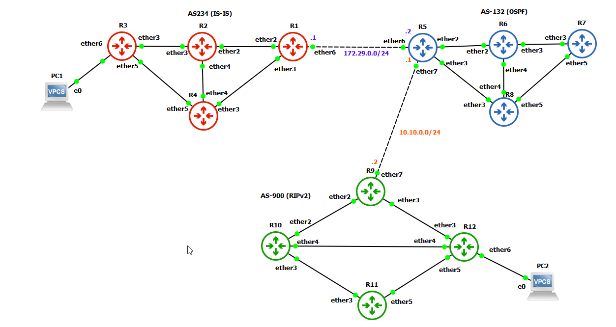
This setup consists of 12 routers, grouped into three autonomous systems (AS234, AS-132, and AS-900). Each of our autonomous systems will use a distinct internal routing protocol, but communication between them will occur via the sole exterior gateway protocol, BGP. AS-234 will use the IS-IS routing protocol, AS-132 will use the OSPF routing protocol, and AS-900 will use RIPv2 routing protocol. To start you out in GNS3, we've created an export of the setup shown above.

Connections between the routers is defined by the following:

Source Router Source Port Destination Router Destination Port
AS-234 (IS-IS)
R1 ether2 R2 ether2
R1 ether3 R4 ether3
R2 ether3 R3 ether3
R2 ether4 R4 ether4
R3 ether5 R4 ether5
AS-132 (OSPF)
R5 ether2 R6 ether2
R5 ether3 R8 ether3
R6 ether3 R7 ether3
R6 ether4 R8 ether4
R7 ether5 R8 ether5
AS-900 (RIPv2)
R9 ether2 R10 ether2
R9 ether3 R12 ether3
R10 ether3 R11 ether3
R10 ether4 R12 ether4
R11 ether5 R12 ether5
Inter-AS BGP Connections
R1 ether6 R5 ether6
R5 ether7 R9 ether7

To establish the router connections and configurations for IS-IS, OSPF, RIPv2, and BGP as detailed, you'll need to configure the interfaces and routing protocols on each MikroTik router. Below is the code to set up each router with their respective connections and protocols.

Also, we have added two VPCS machines, one to ether6 on R3 and another to ether6 on R12 to test. We have not added these machines to the file above – this is part of your assignment if you choose to start with the file above.

IGP Router Configurations for AS Communication


AS-234 (IS-IS)
Router 1 (R1) Configuration

# Interface Setup
/interface bridge add name=bridge1
/ip address add address=172.29.0.1/24 network=172.29.0.0 interface=ether6
/ip address add address=192.168.1.1/24 network=192.168.1.0 interface=bridge1
/interface bridge port add bridge=bridge1 interface=ether2
/interface bridge port add bridge=bridge1 interface=ether3

# IS-IS Setup (see IS-IS System ID note below)
/routing isis instance add name=default system-id=xxxx.xxxx.xxxx areas=yy.yyyy
/routing isis interface-template add instance=default interface=bridge1 levels=l1,l2

# DHCP Server
/ip dhcp-server network add address=192.168.1.0/24 gateway=192.168.1.1
/ip pool add name=dhcp_pool ranges=192.168.1.10-192.168.1.254
/ip dhcp-server add name=dhcp1 address-pool=dhcp_pool disabled=no interface=bridge1 lease-time=10m

# Set system identity
/system identity set name=R1
💡
What is the IS-IS System ID?
Unique Identifier: The IS-IS System ID is a unique 6-byte (48-bit) identifier assigned to each router in an IS-IS network. It is used to uniquely identify each router within the IS-IS routing domain.
Format: The system-id is written as xxxx.xxxx.xxxx.

Purpose of the IS-IS System ID:
Router Identification: The System ID helps in uniquely identifying each router in the IS-IS network, which is crucial for routing decisions and maintaining routing tables.
Neighbor Relationships: It is used in the establishment of neighbor relationships between IS-IS routers. The System ID is part of the IS-IS Hello packet and helps in recognizing and establishing communication with other routers.
Route Calculation: The System ID is used in the route calculation process to ensure that routing information is correctly processed and exchanged between routers.

For the system-id we are going to use the MAC address of the bridge interface. To retrieve it we can use the command
/interface bridge print detail. For example, if the mac is 0c:c7:83:09:00:01, we just write it is 0cc7.8309.0001
💡
What is the IS-IS Area Address?
The IS-IS Area Address is a hierarchical identifier used to define a specific area or domain within an IS-IS network. It helps in the organization and routing of data within and between these areas.
Format: The area address is written asxx.xxxx

Purpose of the IS-IS Area Address:
Network Segmentation:
The Area Address helps in dividing the network into areas. Each area can be managed independently, reducing the complexity of routing within each area and helping in scaling the network.
Routing Efficiency:
By organizing routers into areas, IS-IS can limit the propagation of routing information. Only summary information about routes is shared between areas, which helps in reducing the amount of routing data that each router needs to process.
Hierarchical Routing:
IS-IS supports a hierarchical routing model with Level 1 and Level 2:

Level 1: Routers within the same area use Level 1 routing. They share detailed routing information with each other.
Level 2: Routers between different areas use Level 2 routing. They handle summary information and route traffic between areas.

For this exercise, we are just going to use 49.0001 for the area id. Why? For interoperability, 49. is the ID that is used to signal that this is an IP network, and the lower part of the ID is used to identify the network.

Router 2 (R2) Configuration

# Interface Setup
/interface bridge add name=bridge1
/ip address add address=192.168.1.2/24 network=192.168.1.0 interface=bridge1
/interface bridge port add bridge=bridge1 interface=ether2
/interface bridge port add bridge=bridge1 interface=ether3
/interface bridge port add bridge=bridge1 interface=ether4

# IS-IS Setup
/routing isis instance add name=default system-id=xxxx.xxxx.xxxx areas=yy.yyyy
/routing isis interface-template add instance=default interface=bridge1 levels=l1,l2

# DHCP Client
/ip dhcp-client add interface=bridge1

# Set system identity
/system identity set name=R2

Router 3 (R3) Configuration

# Interface Setup
/interface bridge add name=bridge1
/ip address add address=192.168.1.3/24 network=192.168.1.0 interface=bridge1
/interface bridge port add bridge=bridge1 interface=ether3
/interface bridge port add bridge=bridge1 interface=ether5
/interface bridge port add bridge=bridge1 interface=ether6

# IS-IS Setup
/routing isis instance add name=default system-id=xxxx.xxxx.xxxx areas=yy.yyyy
/routing isis interface-template add instance=default interface=bridge1 levels=l1,l2

# DHCP Client
/ip dhcp-client add interface=bridge1

# Set system identity
/system identity set name=R3

Router 4 (R4) Configuration

# Interface Setup
/interface bridge add name=bridge1
/ip address add address=192.168.1.4/24 network=192.168.1.0 interface=bridge1
/interface bridge port add bridge=bridge1 interface=ether3
/interface bridge port add bridge=bridge1 interface=ether4
/interface bridge port add bridge=bridge1 interface=ether5

# IS-IS Setup
/routing isis instance add name=default system-id=xxxx.xxxx.xxxx areas=yy.yyyy
/routing isis interface-template add instance=default interface=bridge1 levels=l1,l2

# DHCP Client
/ip dhcp-client add interface=bridge1

# Set system identity
/system identity set name=R4

Verify Setup

From router R1, issue the following command:

/routing/isis/neighbor print

This should show the other routers (R2, R3, and R4) for both levels l1 and l2 as shown in the screenshot below.

perform the same from routers R2,R3, and R4 and you should see the other routers as neighbors.

IS-IS (Intermediate System to Intermediate System)

  • Type: Link-State Protocol
  • Area Design: Supports hierarchical network design with multiple levels (Level 1 and Level 2 areas).
  • Metric: Uses a single metric (cost) to determine the best path.
  • Transport: Operates directly over the Data Link Layer (Layer 2), independent of the Network Layer (Layer 3).
  • Scalability: Highly scalable, suitable for large networks.
  • Convergence: Fast convergence due to its link-state nature.
  • Complexity: More complex to configure and manage compared to simpler protocols like RIPv2.
  • Deployment: Common in large ISP networks and service provider environments due to its scalability and robust design.

When to Use IS-IS

  • Large ISP Networks: IS-IS is designed to handle large, complex networks with a high number of routers and areas. Its scalability and robustness make it ideal for ISPs and large-scale service provider networks.
  • Service Provider Environments: The hierarchical design and fast convergence of IS-IS make it suitable for service providers that require efficient and reliable routing.
  • Networks Needing Layer 2 Independence: IS-IS operates directly over Layer 2, making it a good choice for environments where Layer 3 independence is beneficial.

AS-132 (OSPF)
Router 5 Configuration

# Interface Setup
/interface bridge add name=bridge1
/ip address add address=172.29.0.2/24 network=172.29.0.0 interface=ether6
/ip address add address=10.10.0.1/24 network=10.10.0.0 interface=ether7
/ip address add address=192.168.2.1/24 interface=bridge1
/interface bridge port add bridge=bridge1 interface=ether2
/interface bridge port add bridge=bridge1 interface=ether3

# OSPF Setup
/routing ospf instance add name=default version=2 router-id=192.168.2.1
/routing ospf area add name=backbone area-id=0.0.0.0 instance=default
/routing ospf interface-template add interface=bridge1 area=backbone

# DHCP Server
/ip dhcp-server network add address=192.168.2.0/24 gateway=192.168.2.1
/ip pool add name=dhcp_pool ranges=192.168.2.10-192.168.2.254
/ip dhcp-server add name=dhcp1 address-pool=dhcp_pool disabled=no interface=bridge1 lease-time=10m

# Set system identity
/system identity set name=R5

Router 6 Configuration

# Interface Setup
/interface bridge add name=bridge1
/ip address add address=192.168.2.2/24 network=192.168.2.0 interface=bridge1
/interface bridge port add bridge=bridge1 interface=ether2
/interface bridge port add bridge=bridge1 interface=ether3
/interface bridge port add bridge=bridge1 interface=ether4

# OSPF Setup
/routing ospf instance add name=default version=2 router-id=192.168.2.2
/routing ospf area add name=backbone area-id=0.0.0.0 instance=default
/routing ospf interface-template add interface=bridge1 area=backbone

# DHCP Client
/ip dhcp-client add interface=bridge1

# Set system identity
/system identity set name=R6

Router 7 Configuration

# Interface Setup
/interface bridge add name=bridge1
/ip address add address=192.168.2.3/24 network=192.168.2.0 interface=bridge1
/interface bridge port add bridge=bridge1 interface=ether3
/interface bridge port add bridge=bridge1 interface=ether5

# OSPF Setup
/routing ospf instance add name=default version=2 router-id=192.168.2.3
/routing ospf area add name=backbone area-id=0.0.0.0 instance=default
/routing ospf interface-template add interface=bridge1 area=backbone

# DHCP Client
/ip dhcp-client add interface=bridge1

# Set system identity
/system identity set name=R7

Router 8 Configuration

# Interface Setup
/interface bridge add name=bridge1
/ip address add address=192.168.2.4/24 network=192.168.2.0 interface=bridge1
/interface bridge port add bridge=bridge1 interface=ether3
/interface bridge port add bridge=bridge1 interface=ether4
/interface bridge port add bridge=bridge1 interface=ether5

# OSPF Setup
/routing ospf instance add name=default version=2 router-id=192.168.2.4
/routing ospf area add name=backbone area-id=0.0.0.0 instance=default
/routing ospf interface-template add interface=bridge1 area=backbone

# DHCP Client
/ip dhcp-client add interface=bridge1

# Set system identity
/system identity set name=R8

Verify Setup

From router R5, issue the following command:

/routing/ospf/neighbor print

This should show the other routers (R6,R7,R8) listed as shown in the screenshot below.

Showing ospf neighbors listed.

perform the same from routers R6,R7,R8 and you should see the other routers as neighbors.

OSPF (Open Shortest Path First)

  • Type: Link-State Protocol
  • Area Design: Supports hierarchical network design with a backbone area (Area 0) and other areas.
  • Metric: Uses cost (based on link speed) as the metric for determining the best path.
  • Transport: Operates over the IP layer (Layer 3).
  • Scalability: Highly scalable, suitable for large enterprise and service provider networks.
  • Convergence: Fast convergence due to its link-state nature.
  • Complexity: Easier to configure and manage compared to IS-IS, but more complex than RIPv2.
  • Deployment: Common in large enterprise networks, data centers, and service provider networks.

When to Use OSPF

  • Large Enterprise Networks: OSPF is well-suited for large enterprises due to its scalability, fast convergence, and support for hierarchical design.
  • Data Centers: OSPF's ability to handle complex topologies and provide fast convergence makes it a good fit for data center networks.
  • Networks Requiring Vendor Interoperability: OSPF is widely supported and standardized, making it a good choice for environments with equipment from multiple vendors.

AS-900 (RIPv2)
Router 9 Configuration

# Interface Setup
/interface bridge add name=bridge1
/ip address add address=10.10.0.2/24 network=10.10.0.0 interface=ether7
/ip address add address=192.168.3.1/24 network=192.168.3.0 interface=bridge1
/interface bridge port add bridge=bridge1 interface=ether2
/interface bridge port add bridge=bridge1 interface=ether3

# RIPv2 Setup
/routing rip instance add name=default redistribute=connected,rip
/routing rip interface-template add interfaces=bridge1 instance=default

# DHCP Server
/ip dhcp-server network add address=192.168.3.0/24 gateway=192.168.3.1
/ip pool add name=dhcp_pool ranges=192.168.3.10-192.168.3.254
/ip dhcp-server add name=dhcp1 address-pool=dhcp_pool disabled=no interface=bridge1 lease-time=10m


# Set system identity
/system identity set name=R9

Router 10 Configuration

# Interface Setup
/interface bridge add name=bridge1
/ip address add address=192.168.3.2/24 interface=bridge1
/interface bridge port add bridge=bridge1 interface=ether2
/interface bridge port add bridge=bridge1 interface=ether3
/interface bridge port add bridge=bridge1 interface=ether4

# RIPv2 Setup
/routing rip instance add name=default redistribute=connected,rip
/routing rip interface-template add interfaces=bridge1 instance=default

# DHCP Client
/ip dhcp-client add interface=bridge1

# Set system identity
/system identity set name=R10

Router 11 Configuration

# Interface Setup
/interface bridge add name=bridge1
/ip address add address=192.168.3.3/24 interface=bridge1
/interface bridge port add bridge=bridge1 interface=ether3
/interface bridge port add bridge=bridge1 interface=ether5

# RIPv2 Setup
/routing rip instance add name=default redistribute=connected,rip
/routing rip interface-template add interfaces=bridge1 instance=default

# DHCP Client
/ip dhcp-client add interface=bridge1

# Set system identity
/system identity set name=R11

Router 12 Configuration

# Interface Setup
/interface bridge add name=bridge1
/ip address add address=192.168.3.4/24 interface=bridge1
/interface bridge port add bridge=bridge1 interface=ether3
/interface bridge port add bridge=bridge1 interface=ether4
/interface bridge port add bridge=bridge1 interface=ether5
/interface bridge port add bridge=bridge1 interface=ether6

# RIPv2 Setup
/routing rip instance add name=default redistribute=connected,rip
/routing rip interface-template add interfaces=bridge1 instance=default

# DHCP Client
/ip dhcp-client add interface=bridge1

# Set system identity
/system identity set name=R12

Verify Setup

From router R9, issue the following command:

/routing/rip/neighbor print

This should show the other routers (R10, R11, R12) listed as shown in the screenshot below.

perform the same from routers R10, R11, R12 and you should see the other routers as neighbors.

RIPv2 (Routing Information Protocol version 2)

  • Type: Distance-Vector Protocol
  • Metric: Uses hop count as the metric (maximum hop count of 15).
  • Transport: Operates over the IP layer (Layer 3).
  • Scalability: Limited scalability due to the maximum hop count of 15, making it suitable for small to medium-sized networks.
  • Convergence: Slower convergence compared to link-state protocols.
  • Complexity: Simple to configure and manage.
  • Deployment: Suitable for small networks, such as small office/home office (SOHO) environments or small enterprise networks.

When to Use RIPv2

  • Small Networks: RIPv2 is best suited for small networks due to its simplicity and ease of configuration.
  • Simple Topologies: In networks with straightforward topologies and limited growth, RIPv2 can be an effective choice.
  • Limited Resources: For networks with routers that have limited processing power and memory, RIPv2's simplicity can be an advantage.

BGP Configuration for AS to AS Communication

These are already defined in the rules above but let's look at the lines from R1, R5, and R9 that establish BGP.

Router 1 (R1 in AS-234) Configuration

/routing bgp connection add name=TO_R5 remote.address=172.29.0.2 as=234 local.role=ebgp local.address=172.29.0.1 multihop=yes

Let's break down the preceding statement:

  • /routing bgp connection add:This is the command to add a new BGP connection configuration. In RouterOS v7, BGP connections are managed under the /routing bgp connection menu.
  • name=TO_R5:This assigns a name to the BGP connection. In this case, the connection is named TO_R5. Naming connections can help you identify and manage multiple BGP connections more easily.
  • remote.address=172.29.0.2:Specifies the IP address of the remote BGP peer. This is the address of the BGP router on the other end of the connection. In this example, the remote BGP peer has the IP address 172.29.0.2.
  • as=234:Indicates the Autonomous System (AS) number of the local autonomous system. AS numbers are used to uniquely identify each network within the BGP protocol. Here, the local BGP peer belongs to AS number 234.
  • local.role=ebgp:Defines the role of the local BGP connection. The role ebgp stands for External BGP, which means this router is connecting to a BGP peer in a different AS. If it were ibgp, it would indicate an Internal BGP connection within the same AS.
  • local.address=172.29.0.1:Sets the local IP address that will be used for the BGP session. This is the IP address on your router that will be used to establish the connection with the remote BGP peer. In this case, the local address is 172.29.0.1.
  • multihop=yes:Enables the multihop feature for the BGP connection. By default, BGP peers need to be directly connected. Enabling multihop allows BGP peering to be established over multiple hops. This is useful in cases where the BGP peer is not directly connected and is reachable through intermediate routers.

Router 5 (R5 in AS-132) Configuration

/routing bgp connection add name=TO_R1 remote.address=172.29.0.1 as=132 local.role=ebgp local.address=172.29.0.2 multihop=yes
/routing bgp connection add name=TO_R9 remote.address=10.10.0.2 as=132 local.role=ebgp local.address=10.10.0.1 multihop=yes

Router 9 (R9 in AS-900) Configuration

/routing bgp connection add name=TO_R5 remote.address=10.10.0.1 as=900 local.role=ebgp local.address=10.10.0.2 multihop=yes

To verify that BGP is working, we can issue the following command on routers R1, R5, and R9

/routing bgp session print

and should see something similar to the following image: (This was taken from router R1)

Now that we have established BGP for external routing, the final step is to advertise the routes that we want to share over BGP. In this case, our AS234 will advertise its 192.168.1.0 network, AS132 will advertise 192.168.2.0 network, and AS900 will advertise 192.168.3.0 network.
First, if we look at our routing table on R1

ip route print

what we see is the following

R1 routing table

similarly, on R5

and on R9

We’ve observed that our BGP links aren’t sharing networks with each other. Currently, each router only knows about the networks directly connected to it. BGP will enable us to share network information across these links. In order to share the networks, we are going to create an address list and share the address list using the BGP output.network parameter.

On Router R1, add the following

/ip firewall address-list add address=192.168.1.0/24 list=BGP-EXT
/routing bgp connection set output.network=BGP-EXT 0

On Router R5, add the following

/ip firewall address-list add address=192.168.2.0/24 list=BGP-EXT
/routing bgp connection set output.network=BGP-EXT 0
/routing bgp connection set output.network=BGP-EXT 1

and on Router R9, add the following

/ip firewall address-list add address=192.168.3.0/24 list=BGP-EXT
/routing bgp connection set output.network=BGP-EXT 0

BGP for Inter-AS Communication

  • Performance:
    • Convergence Time: BGP convergence can be slower than IGPs like OSPF and IS-IS, especially in very large networks. BGP relies on incremental updates and can take time to propagate routing changes.
    • Resource Utilization: BGP can be resource-intensive, especially with large numbers of routes and peers.

This configuration sets up the necessary interfaces, assigns IP addresses, enables the appropriate IGPs, and configures BGP peering between the autonomous systems. Each router is connected to its peers in both its respective IGP and BGP configuration to ensure proper routing and network functionality.

Overall Network Performance and Setup

  • Convergence: The overall network convergence will be influenced by the slowest converging protocol (likely RIPv2 in this case). IS-IS and OSPF will provide rapid convergence within their respective ASes, but changes affecting BGP peering will converge more slowly.
  • Resource Requirements: Expect higher resource utilization (CPU and memory) on routers running IS-IS and OSPF due to the complex nature of these protocols. Routers using RIPv2 will have lower resource requirements.
  • Operational Complexity: Managing a network with multiple routing protocols and BGP peering will require a high level of expertise. Understanding and troubleshooting interactions between IS-IS, OSPF, RIPv2, and BGP will be critical for maintaining network stability.
  • Routing Policies: Effective BGP configuration will be crucial for controlling route advertisement between autonomous systems and ensuring optimal path selection. This involves setting up route maps, prefix lists, and other BGP attributes.

Testing

  1. Configure PC1 and PC2 for DHCP. Right click VPCS (PC1) and click Edit Config and uncomment the dhcp line and save. Perform the same for VPCS (PC2). Start both VPCS appliances.
  2. From PC1, ping 192.168.3.2. Did it succeed?
PC1 ping to 192.168.3.2
  1. From PC2, ping 192.168.1.4. Did it succeed?
PC2 ping to 192.168.1.4

Summary

In this lab, we established 3 separate networks, each one running a different routing protocol. We connected the three networks together using BGP to share the network routing data across each of the networks.
In summary, IS-IS and OSPF will provide robust and scalable routing within their respective autonomous systems, while RIPv2 will offer simplicity and ease of configuration for a smaller AS. BGP will tie these autonomous systems together, allowing for inter-AS communication. Performance will be high within each AS using IS-IS and OSPF, but inter-AS convergence times will depend on BGP. Proper planning, configuration, and ongoing management are key to maintaining optimal network performance.